
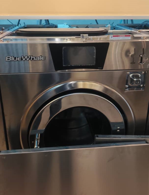
Blue Whale - Installation
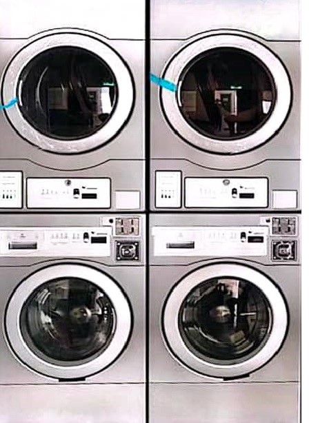
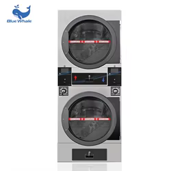
Example: Blue Whale Stack Dryer & Washer
(A) Connection Washer/Dryer
1. Blue Whale machine, the connection is direct and simple. You will see three wires running from the board to the coin acceptor (Black, White, and Red).”
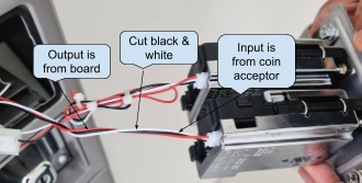
2. As shown in the picture above, cut the Black and White wires between the board and the coin acceptor. Then, connect the input and output using the 4-core wire from the device.
3. Leave Red wire
- Do not cut Red (it’s power). It should remain continuous from board.
4. Cut the Black & White wires
- Cut both Black and White roughly in the middle of their run.
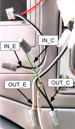
5. Two sides after the cut
-
The ends coming from the board = OUTPUT (to the machine board).
-
Board-White → OUT+
-
Board-Black → OUT−
-
-
The ends going to the coin acceptor = INPUT (from the coin acceptor).
-
Acceptor-White → IN+
-
Acceptor-Black → IN−
-
6. Power ON and test
- Insert a coin/token, If the Coin Read in Node Cloud app shows pulses and the machine credit—done.
7. If it shows “No Pulse Detected”:
-
Confirm IN/OUT are not swapped.
-
Verify + and − on both input and output pairs.
-
Ensure the coin is actually accepted (a rejected coin won’t pulse).
(B) Device Connection - ALPHA-1
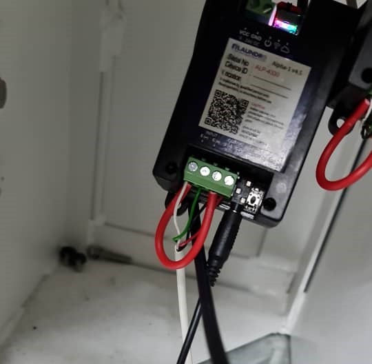
1. Devices will be placed behind the machine by screwing it using a specific screw.
2. Connecting the 4-Core Wire to the Device
-
Connect the 4-core wire to the device according to the terminal markings:
-
Input (IN−, IN+)
-
Output (OUT−, OUT+)
-
-
After wiring, make a loop connection between:
-
IN− (Input negative)
-
OUT− (Output negative)
-
-
Ensure all connections are secured and insulated before powering ON.
________________________________________________________________________________________________________________________________________________
Blue Whale Cashless Machine (Non-Coin Acceptor)
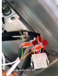
(A) Wire connection Dryer
 Dryer Connector
1. Locate the cashless connector
-
Identify the two output wires shown in your picture:
-
White = Output (−)
-
Green = Output (+)
-
2. Dryer cashless machines with a connector as shown in the picture above, use the output connection only. Tap into the two wires: White (Output Negative −) and Green (Output Positive +), using a 2-core cable from the device.
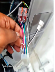
(B) Wire Connection Washer
 Washer connector
1. Locate the cashless connector
-
Identify the two output wires shown in your picture:
-
Pink = Output (−)
-
Red = Output (+)
-
2. Washer cashless machines with a connector as shown in the picture above, use the output connection only. Tap into the two wires: Pink (Output Negative −) and Red (Output Positive +), using a 2-core cable from the device.
(B) Device Connection - ALPHA-1
![]() Quality Note: Looping From Input (-) To (+)
Quality Note: Looping From Input (-) To (+)
1. Devices will be placed behind the machine by screwing it using a specific screw.
2. Connecting the 2-Core Wire to the Device.
-
Connect the 2-core wire to the device according to the markings:
-
Output (OUT−, OUT+)
-
-
After wiring, make a loop connection between:
-
INPUT− (Input negative)
-
INPUT− (Input positive)
-
-
Ensure all connections are secured and insulated before powering ON.
________________________________________________________________________________________________________________________________________________
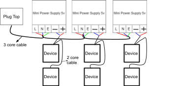
Power Supply Connection for Blue Whale Machine
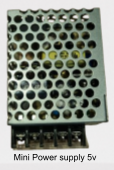
![]() Quality Note: 5v Power Supply Required
Quality Note: 5v Power Supply Required
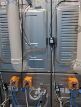
1. For the Blue Whale machine, each device must have its own dedicated power supply. For example, one device requires one power supply. If there are five devices, you must use five separate power supply connections, as shown in the image above.
________________________________________________________________________________________________________________________________________________
Blue Whale New Version
DRYER
1) The new version will use a specific harness cable, and the deice power can take from machine .
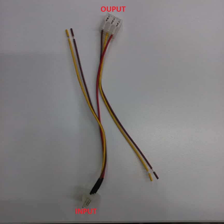 HARNESS CABLE
2) Before we start install device, prepare both a 4-core and a 2-core cable for connecting the device.
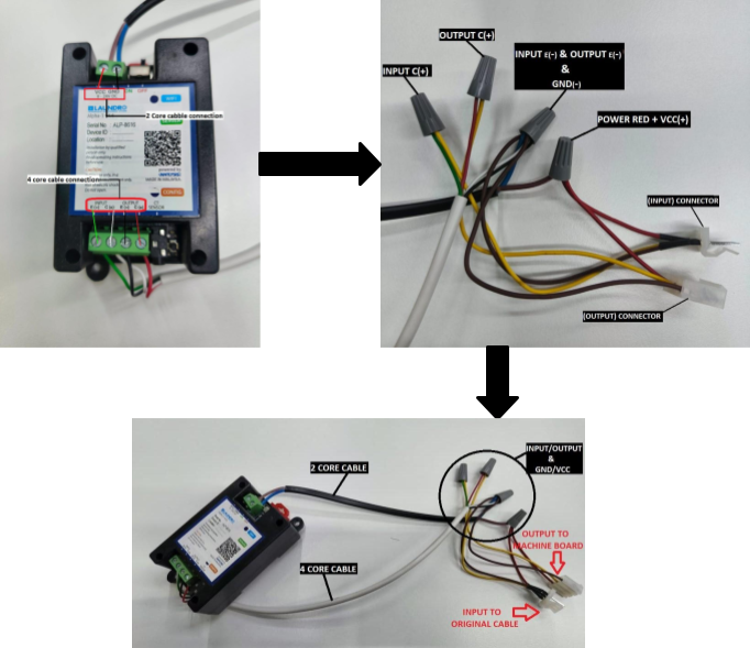 INPUT/OUTPUT & GND-/VCC+
3) Step by step connection return below.
- Use a 4-core cable to connect the device’s INPUT E(-)/C(+) and OUTPUT E(-)/C(+) points.
- From the device, take INPUT E(-), OUTPUT E(-), and GND (-), join them together, and connect to the 'harness cable' INPUT and OUTPUT connections (CHOCLATE ).
- From the device, take the INPUT C(+) and connect it to the 'harness cable' INPUT (YELLOW ).
- From the device, take the OUTPUT C(+) and connect it to the 'harness cable' OUTPUT(YELLOW ).
- From the device, take the VCC (+) and connect it to the red wire on 'the harness cable' (RED )
4) Follow the step-by-step connection procedure and connect it to the machine board.
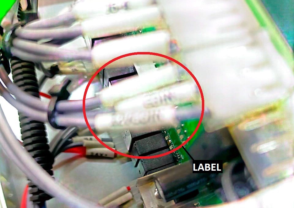
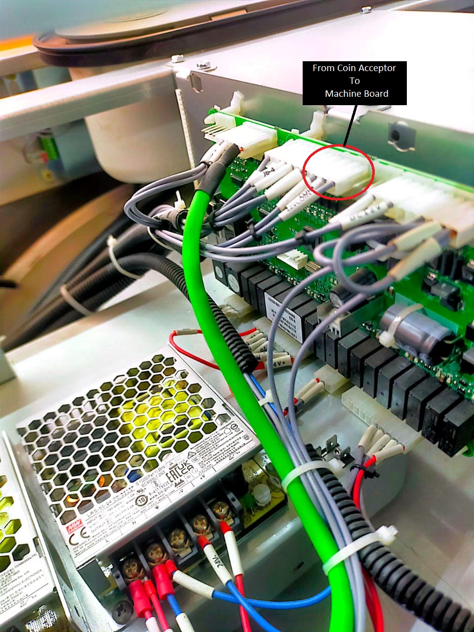
- If you are not sure which connector to use, refer to the red-circled label on the cable in the picture. The coin acceptor cable has the same label, so you can match the labels to identify the correct connector on the board.
- Find the correct connector by pulling out the cable. Connect it to the harness cable INPUT, then connect the harness cable OUTPUT to the board.
WASHER
1) The new version will use a specific harness cable, and the deice power can take from machine .
2) Before we start install device, prepare both a 4-core and a 2-core cable for connecting the device.
 Device To Harness Cable Connection
3) Step by step connection return below.
- Connect the device INPUT E(-) (White wire) to the harness cable INPUT (Brown wire).
- Connect the device INPUT C(+) (Green wire) to the harness cable INPUT (Yellow wire).
- Connect the device OUPUT E(-) (Black wire) to the harness cable OUTPUT (Brown wire).
- Connect the device OUTPUT C(+) (Red wire) to the harness cable OUTPUT (Yellow wire).
4) Follow the step-by-step connection procedure and connect it to the machine board.
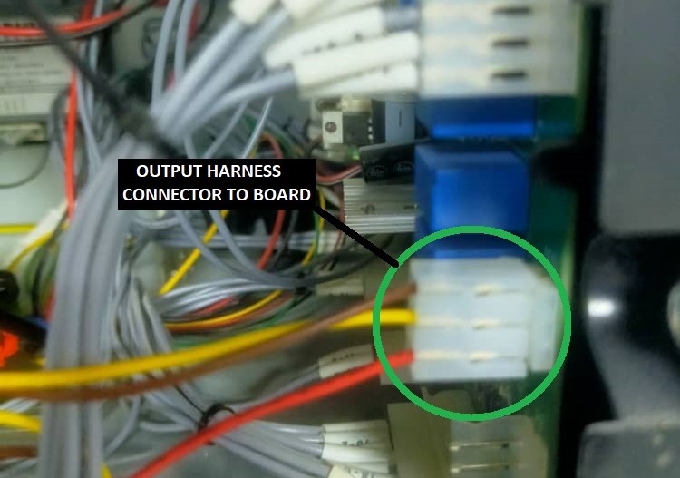
WASHER BOARD ORIGINAL CONECCTION
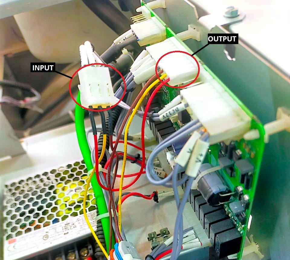 WASHER BOARD HARNESS CABLE CONNECTION
5) Find the correct connector by pulling out the cable. Connect it to the harness cable INPUT, then connect the harness cable OUTPUT to the board.
6) The device will receive power from the machine’s existing power supply. Since there are two power supplies present, use the one that provides 12V.
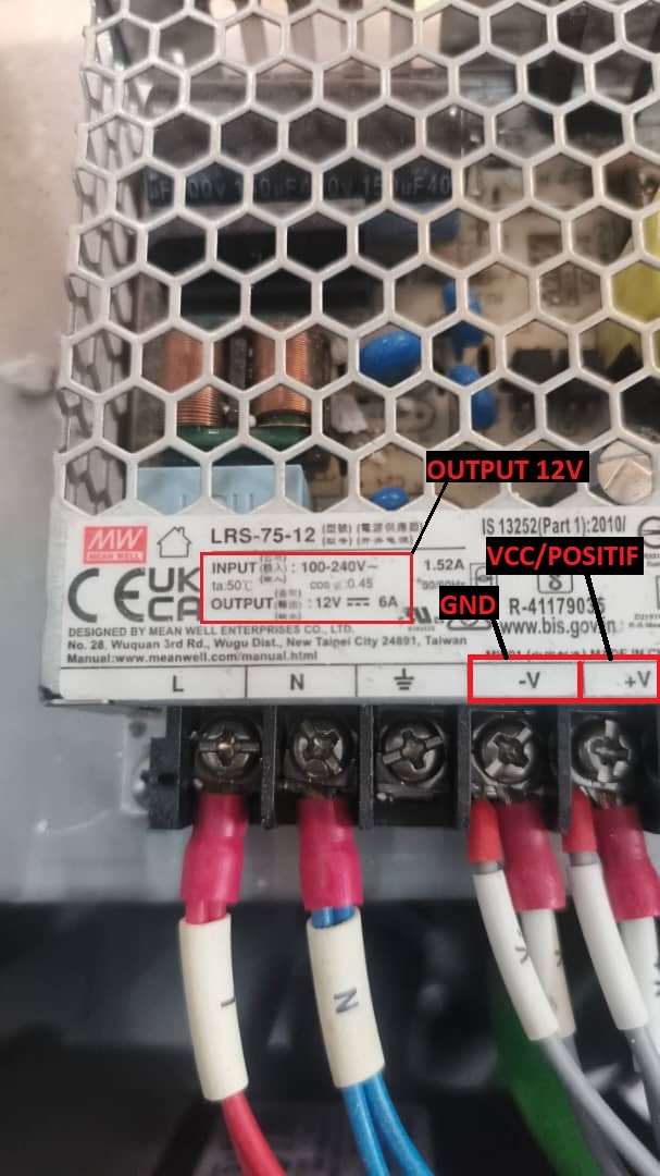 Machine Power Supply
7) After completing all the connections, power on the machine. The device’s blue indicator light will begin blinking.
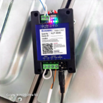
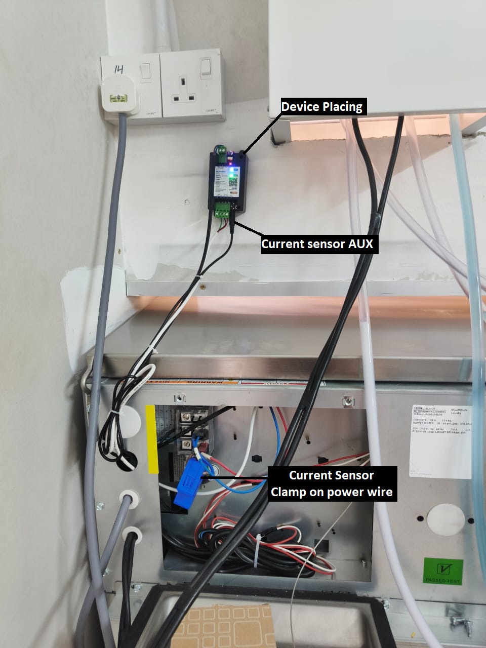 CURRENT SENSOR & DEVICE PLACING
8) You may place the device in the position shown in the picture, or any safer location where it will not be damaged.
9) Clamp the current sensor onto the machine’s positive power wire, and connect the AUX plug to the device.