**Be cautious before installation**
1. ##### **No pinch and wire for the main board while installing.** 2. ##### **Turn off the machine electricity while during installation.** 1\) Remove the screw at the marked position shown in the picture. [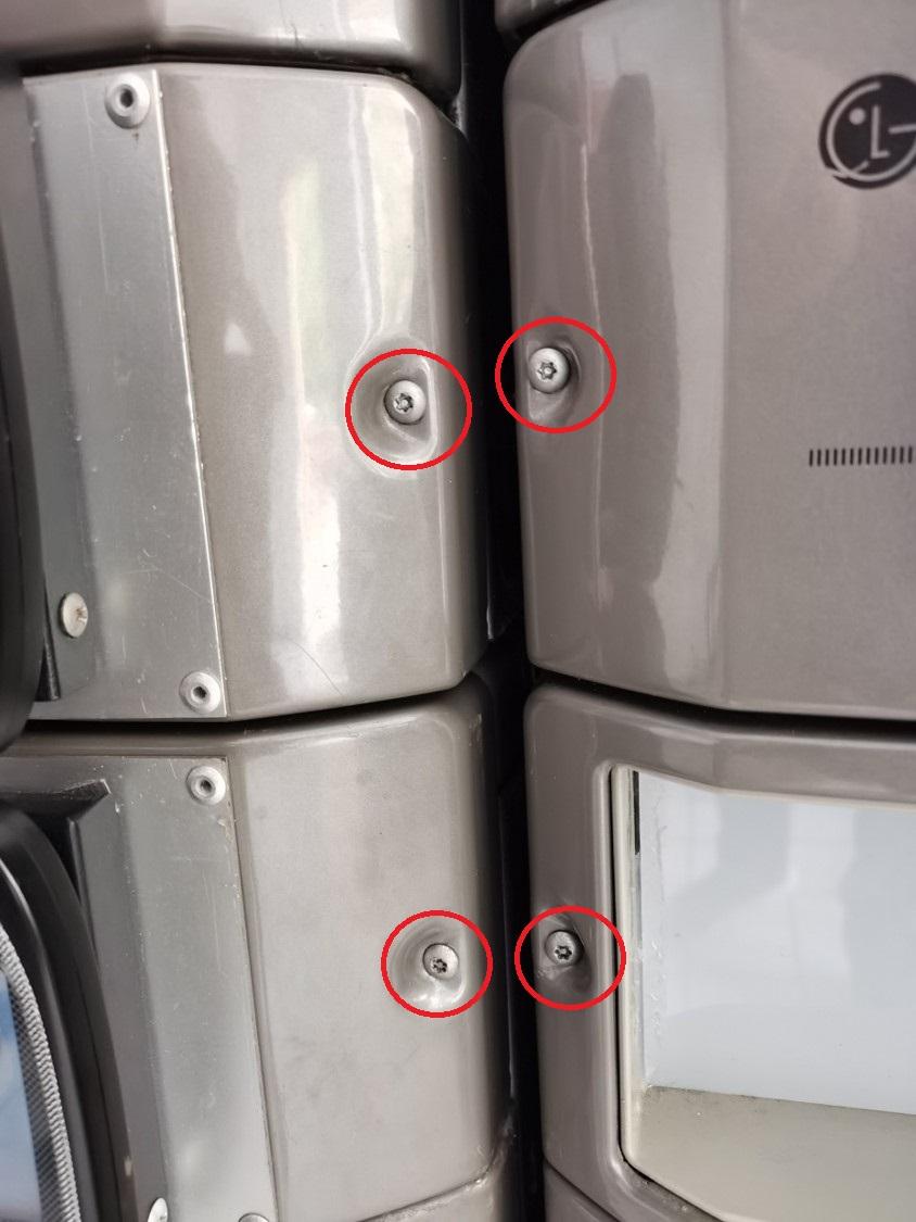T20 SCREW](https://docs.antlysis.com/uploads/images/gallery/2025-11/0LQzl196JYNfxkPn-lg-unscrew.jpg) 2\) After opening the board casing, the board connections will be visible. Remove the connectors and store the board casing safely. [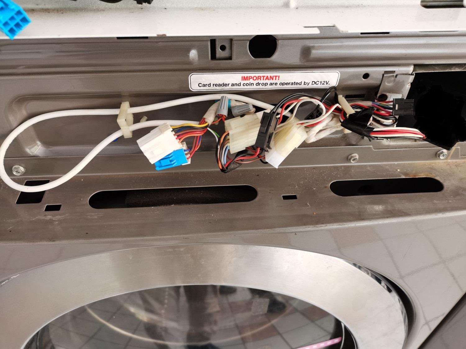ORIGINAL LG CONNECTION](https://docs.antlysis.com/uploads/images/gallery/2025-11/Y6m4pFzsAoXMSJLt-board-con.jpg) 3\) LG Cashless system uses a specific harness cable. ##### **LG CASHLESS HARNESS CABLE** **[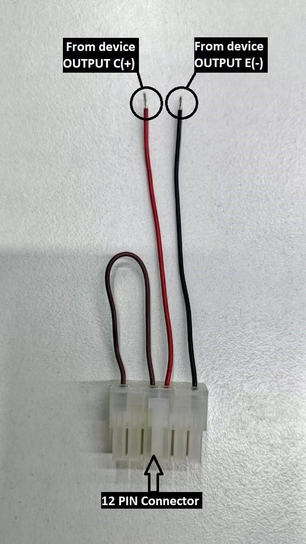](https://docs.antlysis.com/uploads/images/gallery/2025-11/aMAh2FkTIwAgHCHF-lg-harness.jpg)****[LG HARNESS CABLE ](https://docs.antlysis.com/uploads/images/gallery/2025-11/aMAh2FkTIwAgHCHF-lg-harness.jpg)** 4\) The machine connection has a 12-pin connector. Remove it and connect it to the 12-pin harness cable connector. 5\) Use a 4-core alarm cable from device, but only the red and black wires are required. Connect these two wires to the harness cable. #### **Device Connection** [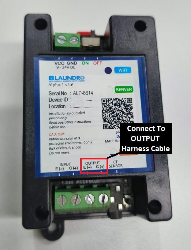](https://docs.antlysis.com/uploads/images/gallery/2025-11/bGgkSkJtVgkU5uDq-device.jpg) [Device OUTPUT Connection](https://docs.antlysis.com/uploads/images/gallery/2025-11/bGgkSkJtVgkU5uDq-device.jpg) 6\) Using a 4-core cable, connect it to the device OUTPUT terminals **E (–)** and **C (+)**. ##### **Connection from device to harness cable** - ##### **From device E ( - ) <> Harness cable ''BLACK''** - ##### **From device C (+) <> Harness cable ''RED''** # Speed Queen v1- Installation ### Speed Queen Single Washer & Stack washer / Dryer ##### Type off Speed Queen Machine [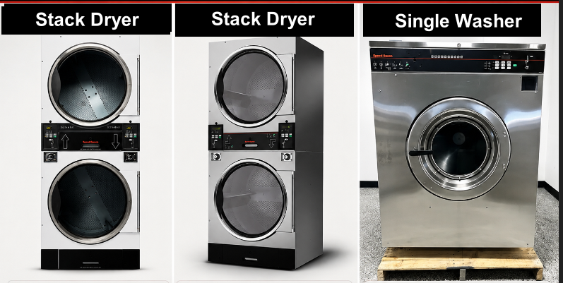](https://docs.antlysis.com/uploads/images/gallery/2026-05/9tCiI3Oxxa5Xuvfj-image.png)[](https://docs.antlysis.com/uploads/images/gallery/2026-05/EoIvJvSrwHC68xyP-image.png) --- #### #### “Types of installation for Speed Queen machines” #### **Cashless Installation-** Speed Queen Stack Washer/Dryer STGNCASP116TW01 **☞ Cashless connection for E-payment transactions only, suitable for machines without a coin acceptor or machines with a coin acceptor where token capture is not required.** **1)** Open the motherboard casing using the specific machine key provided. [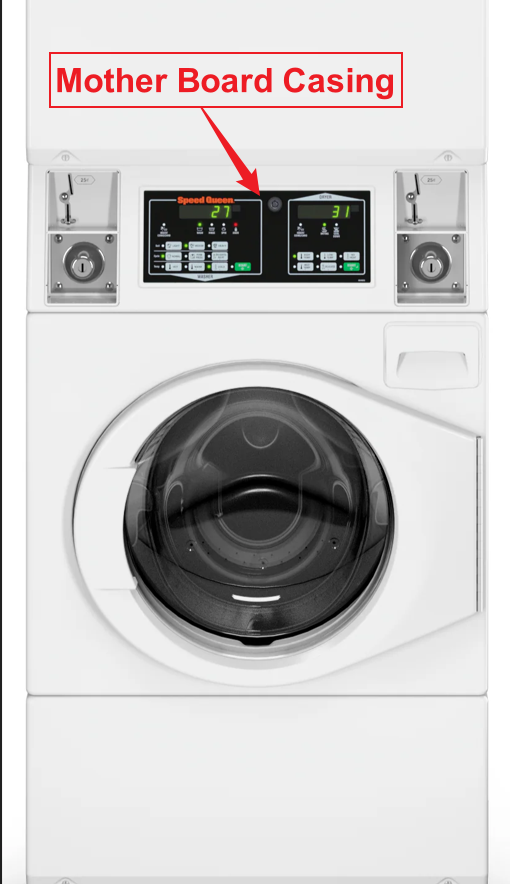](https://docs.antlysis.com/uploads/images/gallery/2026-05/GsfqgH55R7YfAB11-image.png) **2)** Pull the wires from the front to the back of the machine, where you will be placing the Alpha-1 device. 👉 **For the Speed Queen machine, it is recommended to use 1.5 mm thick cables for the OUTPUT (-/+) connection.** **3)** On the machine, you will see two identical male connectors — one yellow and one red. 👉 **It is recommended to use the red male connector.** [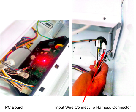](https://docs.antlysis.com/uploads/images/gallery/2025-08/SWqPUwyisG5KR2fv-image11.png) **4)** We provide a specific female harness connector to connect to the machine’s male connector. **5)** Connect the Output Harness to the cable from the device, ensuring that the output negative (–) and positive (+) are correctly connected. [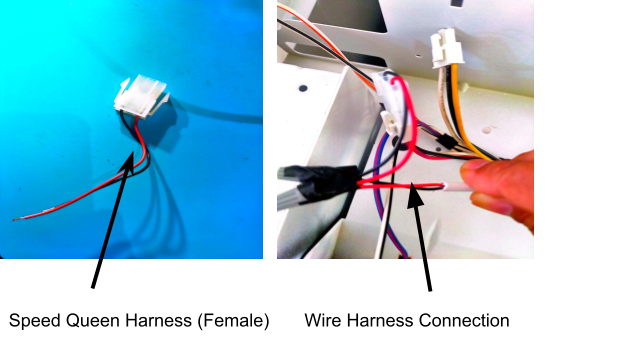](https://docs.antlysis.com/uploads/images/gallery/2025-08/RJY9xzvbNpbEVxBg-image101.png) --- ##### **Coin Acceptor Installation**Quality Note - To Do Looping Input (-) to (+)
--- ''Speed Queen Stack Dryer Connection'' **1)** For this machine model, the same harness connector will be used as other Speed Queen models. However, the wire connection from the Alpha-1/Device is slightly different. 👉 **For the Speed Queen machine, it is recommended to use 1.5 mm thick cables for the OUTPUT (-/+) connection.** **2)** Open both the upper and lower coin acceptor casings. [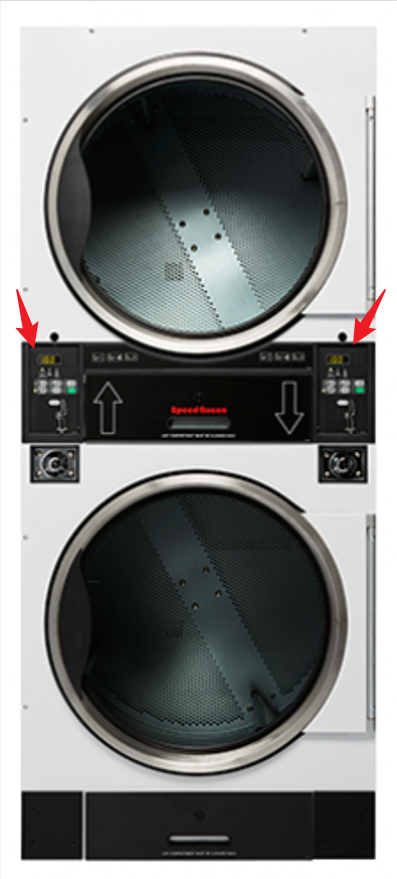](https://docs.antlysis.com/uploads/images/gallery/2026-05/o0MIJCfx2IzTzkG3-image.png) **3)** After opening the casing, you will see 4 screws at the end. Remove all 4 screws to access the inside of the machine. [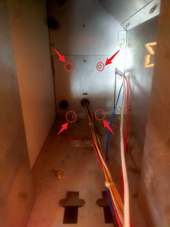](https://docs.antlysis.com/uploads/images/gallery/2026-05/hTWeacIco4wlOgef-image.png) **4)** To pull the wire, start from the upper side of the casing. **5)** The diagram below shows how the wire should be pulled in side the machine from the front to the back, where the device will be placed. [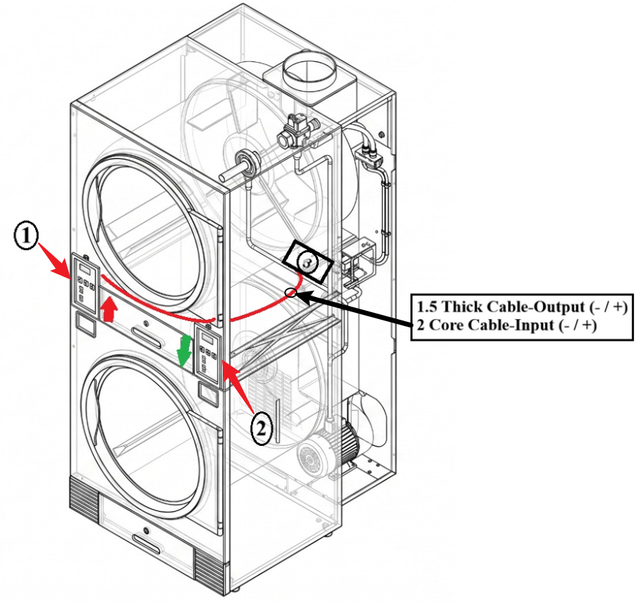](https://docs.antlysis.com/uploads/images/gallery/2026-05/cW9zsVvmdzEYhqa6-image.png) **6)** Cable Routing Steps for **Left/UP** (1) (Refer to Picture) **1.** Route the cable from the top side (1) to the bottom side (2). **2.** Pull the cable to the back of the machine. **3.** Locate the small hole (3). [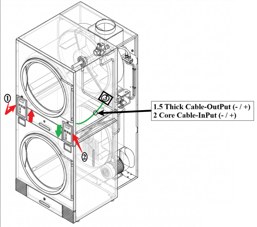](https://docs.antlysis.com/uploads/images/gallery/2026-05/uXpqxvvnR5jiLuA1-image.png) **7)** Cable Routing Steps for **Right/Down** (2) (Refer to Picture) **1.** From the (2) bottom side, pull the wire straight to the (3) rear section.**There are other hoses passing near this hole, so pull carefully.**
**7)** Feed/push the cable through the small hole (3) until you can see the cable coming out at the back of the machine. [](https://docs.antlysis.com/uploads/images/gallery/2026-05/Fx4Za5KW38apAxI2-image.png) **8)** Pull the cable through hole (3) until it reaches the device installation location. --- ##### Click this link to next step: # IPSO - Installation IPSO Washer/Dryer **Example: Dryer** [](https://docs.antlysis.com/uploads/images/gallery/2025-08/if2VVd55xOyH1Cfi-image44.png) **Example: Washer** **[](https://docs.antlysis.com/uploads/images/gallery/2025-08/3FaJswbgi5RpJYYg-image26.png)** ##### **Harness Installation** 1. The IPSO machine has input and output connectors. Unplug them and connect them to the harness connector. [](https://docs.antlysis.com/uploads/images/gallery/2025-08/pPLkiLgemoNVhYVG-image62.png) **Use thick wire 1mm or 1.5mm to connect Output (No3)** 2\. From the harness connector, connect the output and input to the 4-core wire from the device, following the input and output terminals. Ensure that the input and output negative (–) and positive (+) connections are correct. 3\. For this machine, use a 1 mm or 1.5 mm thick cable for the output to ensure a better pulse signal. [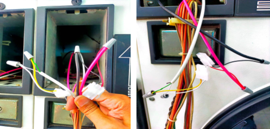](https://docs.antlysis.com/uploads/images/gallery/2025-08/o8wiSUJ6MehxcaPw-image72.png) # Go World - Installation (A) From Chinese brands such as **Go World**, **Octopus**, and **Oasis.** **Example: Go World Stack Washer/Dryer** **[](https://docs.antlysis.com/uploads/images/gallery/2025-08/oedSYUXGjTMdU9KD-image97.jpg)** ##### **Washer/Dryer Harness connection** 1\. These models are equipped with a specific harness connector designed to connect to the machine’s board. 2\. Connect the wire harness according to the input and output shown in the picture below from the Alpha-1 device . [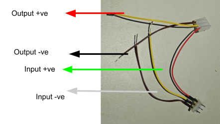](https://docs.antlysis.com/uploads/images/gallery/2025-08/e2FrAVJNZ8XfnelC-image94.png) (B) **Go world dryer** 3\. As shown in the picture below, remove the connector from the board, connect the output to the board, and connect the input to the removed connector. [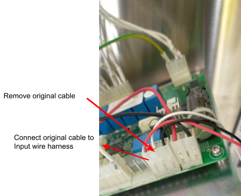](https://docs.antlysis.com/uploads/images/gallery/2025-08/BD3yP1fDh4Ij3r0V-image42.png)[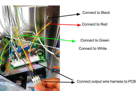](https://docs.antlysis.com/uploads/images/gallery/2025-08/YjqnCWTcvjggoHap-image47.png) (C) **Go World Washer** 4\. As shown in the picture below, remove the connector from the board, connect the output to the board, and connect the input to the removed connector. [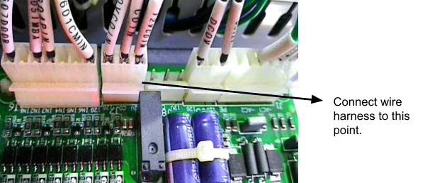](https://docs.antlysis.com/uploads/images/gallery/2025-08/jBUKHF5AbXxrDBaX-image40.png) 5\. Connect the input and output harness cables to the 4-core wire from the Alpha-1 device. [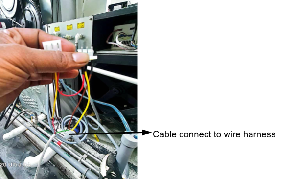](https://docs.antlysis.com/uploads/images/gallery/2025-08/VjJ3KMF5epJkQmVS-image15.png) \_\_\_\_\_\_\_\_\_\_\_\_\_\_\_\_\_\_\_\_\_\_\_\_\_\_\_\_\_\_\_\_\_\_\_\_\_\_\_\_\_\_\_\_\_\_\_\_\_\_\_\_\_\_\_\_\_\_\_\_\_\_\_\_\_\_\_\_\_\_\_\_\_\_\_\_\_\_\_\_\_\_\_\_\_\_\_\_\_\_\_\_\_\_\_\_\_\_\_\_\_\_\_\_\_\_\_\_\_\_\_\_\_\_\_\_\_\_\_\_\_\_\_\_\_\_\_\_\_\_\_\_\_\_\_\_\_\_\_\_\_\_\_\_ (D) **Looping in Alpha-1 for both Washer/Dryer** 6\. Loop the input negative( - ) and output negative( - ) to a common ground connection. [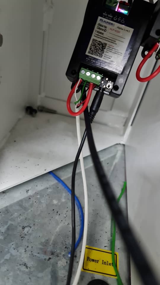](https://docs.antlysis.com/uploads/images/gallery/2025-08/QJhqQ65dZ5q9lhiu-image18.jpg) # Fargo - Installation **Example: Fargo Wire Harness** **[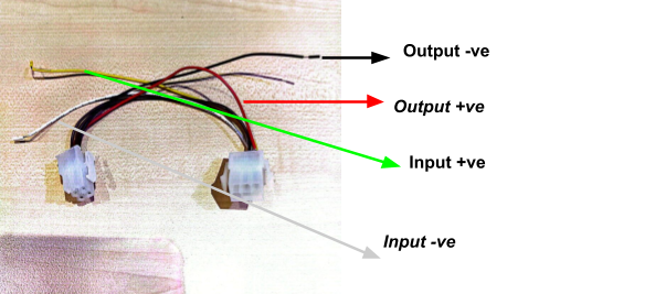](https://docs.antlysis.com/uploads/images/gallery/2025-08/e7QFlYToxmMyMwmN-image82.png)** ##### **Fargo Harness connection Washer/Dryer** **[](https://docs.antlysis.com/uploads/images/gallery/2025-08/Zd6hyaG4ihABmB1Q-image24.png)** **1. The Fargo machine comes with a specific connector. The coin acceptor cable from the machine also has a connector—remove it, then connect it to the provided wire harness, matching the male and female ends or the input and output connectors accordingly.** **2. Connect the wire harness’s input and output lines to the 4-core wiring from the Alpha-1 device.** **Example: Input & Output Connections** **[](https://docs.antlysis.com/uploads/images/gallery/2025-08/M0Eod6NDAb95Rk3D-image3.png)** # Blue Whale - Installation ##### **Example: Blue Whale Stack Dryer & Washer** **[](https://docs.antlysis.com/uploads/images/gallery/2025-08/tawvm8p1C3Pq6KvP-image74.jpg)** ##### **(A) Connection Washer/Dryer** **1.** Blue Whale machine, the connection is direct and simple. You will see three wires running from the board to the coin acceptor (Black, White, and Red).” [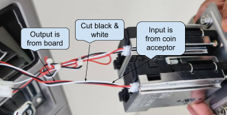](https://docs.antlysis.com/uploads/images/gallery/2025-08/DmucGGMP4JMo8Oit-image33.png)[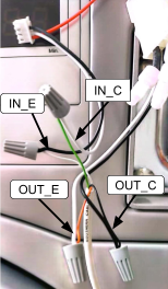](https://docs.antlysis.com/uploads/images/gallery/2025-08/u7MPJ0CJRO1Ul9WS-image65.png) 2\. As shown in the picture above, cut the Black and White wires between the board and the coin acceptor. Then, connect the input and output using the 4-core wire from the device. 3\. Leave Red wire - **Do not cut Red** (it’s power). It should remain continuous from board. 4\. Cut the Black & White wires - Cut both **Black** and **White** roughly in the middle of their run. 5\. Two sides after the cut - The ends **coming from the board** = **OUTPUT** (to the machine board). - Board-White → **OUT+** - Board-Black → **OUT−** - The ends **going to the coin acceptor** = **INPUT** (from the coin acceptor). - Acceptor-White → **IN+** - Acceptor-Black → **IN−** **6. Power ON and test** - Insert a coin/token, If the Coin Read in Node Cloud app shows pulses and the machine credit—done. ****7. If it shows **“No Pulse Detected”**:**** - Confirm **IN/OUT are not swapped**. - Verify **+ and −** on both input and output pairs. - Ensure the coin is actually **accepted** (a rejected coin won’t pulse). ##### **(B) Device Connection - ALPHA-1** [](https://docs.antlysis.com/uploads/images/gallery/2025-08/qKizKBaZV0NbzO22-image59.png)[](https://docs.antlysis.com/uploads/images/gallery/2025-08/h9vnDFBWihX20CTD-image18.jpg) 1**.** Devices will be placed behind the machine by screwing it using a specific screw**.** 2\. Connecting the 4-Core Wire to the Device 1. Connect the **4-core wire** to the device according to the terminal markings: - **Input (IN−, IN+)** - **Output (OUT−, OUT+)** 2. After wiring, make a **loop connection** between: - **IN− (Input negative)** - **OUT**− **(Output negative)** 3. Ensure all connections are secured and insulated before powering ON. \_\_\_\_\_\_\_\_\_\_\_\_\_\_\_\_\_\_\_\_\_\_\_\_\_\_\_\_\_\_\_\_\_\_\_\_\_\_\_\_\_\_\_\_\_\_\_\_\_\_\_\_\_\_\_\_\_\_\_\_\_\_\_\_\_\_\_\_\_\_\_\_\_\_\_\_\_\_\_\_\_\_\_\_\_\_\_\_\_\_\_\_\_\_\_\_\_\_\_\_\_\_\_\_\_\_\_\_\_\_\_\_\_\_\_\_\_\_\_\_\_\_\_\_\_\_\_\_\_\_\_\_\_\_\_\_\_\_\_\_\_\_\_\_ ### Blue Whale Cashless Machine (Non-Coin Acceptor) ##### (A) Wire connection Dryer [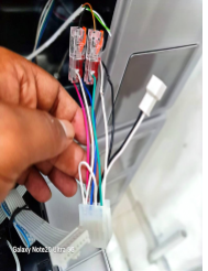Dryer Connector](https://docs.antlysis.com/uploads/images/gallery/2025-08/CQRLcFRPfnjyYPnA-blue-wahle-dryer.png) ***1.* Locate the cashless connector** - Identify the two output wires shown in your picture: - **White = Output (−)** - **Green = Output (+)** **2.** Dryer cashless machines with a connector as shown in the picture above, use the output connection only. Tap into the two wires: White (Output Negative −) and Green (Output Positive +), using a 2-core cable from the device. ##### (B) Wire Connection Washer [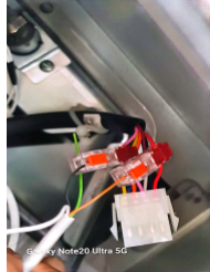Washer connector](https://docs.antlysis.com/uploads/images/gallery/2025-08/R50Sr5W2lRsKzYwt-blue-whale-washer.png) ***1.* Locate the cashless connector** - Identify the two output wires shown in your picture: - **Pink = Output (−)** - **Red = Output (+)** **2.** Washer cashless machines with a connector as shown in the picture above, use the output connection only. Tap into the two wires: Pink (Output Negative −) and Red (Output Positive +), using a 2-core cable from the device. ##### **(B) Device Connection - ALPHA-1** **[](https://docs.antlysis.com/uploads/images/gallery/2025-08/W9wbj347kN20uvdS-image57.png)[Quality Note: Looping From Input (-) To (+)](https://docs.antlysis.com/uploads/images/gallery/2025-08/DB9NMeDHqpgtJibo-ngqn3dgwxmecvvkx-image22.png)** 1**.** Devices will be placed behind the machine by screwing it using a specific screw**.** 2\. Connecting the 2-Core Wire to the Device. 1. Connect the 2**-core wire** to the device according to the markings: - **Output (OUT−, OUT+)** 2. After wiring, make a **loop connection** between: - **INPUT− (Input negative)** - **INPUT**− **(Input positive)** 3. Ensure all connections are secured and insulated before powering ON. \_\_\_\_\_\_\_\_\_\_\_\_\_\_\_\_\_\_\_\_\_\_\_\_\_\_\_\_\_\_\_\_\_\_\_\_\_\_\_\_\_\_\_\_\_\_\_\_\_\_\_\_\_\_\_\_\_\_\_\_\_\_\_\_\_\_\_\_\_\_\_\_\_\_\_\_\_\_\_\_\_\_\_\_\_\_\_\_\_\_\_\_\_\_\_\_\_\_\_\_\_\_\_\_\_\_\_\_\_\_\_\_\_\_\_\_\_\_\_\_\_\_\_\_\_\_\_\_\_\_\_\_\_\_\_\_\_\_\_\_\_\_\_\_ ### Power Supply Connection for Blue Whale Machine [](https://docs.antlysis.com/uploads/images/gallery/2025-08/MI4Vgw6I1VVyIXwT-image66.png)[](https://docs.antlysis.com/uploads/images/gallery/2025-08/gqkmLYpjf7cghDOV-image2.png) [Quality Note: 5v Power Supply Required](https://docs.antlysis.com/uploads/images/gallery/2025-08/DB9NMeDHqpgtJibo-ngqn3dgwxmecvvkx-image22.png) 1\. For the Blue Whale machine, each device must have its own dedicated power supply. For example, one device requires one power supply. If there are five devices, you must use five separate power supply connections, as shown in the image above. [⚠️ **Safety Notice** “Before switching on the power, always ensure that all wires from the main supply to the power supply are properly connected and securely fastened to prevent short circuits, sparks, or damage to the device.”](https://docs.antlysis.com/uploads/images/gallery/2025-08/7QBhrwxQUMDn97OZ-image19.png) \_\_\_\_\_\_\_\_\_\_\_\_\_\_\_\_\_\_\_\_\_\_\_\_\_\_\_\_\_\_\_\_\_\_\_\_\_\_\_\_\_\_\_\_\_\_\_\_\_\_\_\_\_\_\_\_\_\_\_\_\_\_\_\_\_\_\_\_\_\_\_\_\_\_\_\_\_\_\_\_\_\_\_\_\_\_\_\_\_\_\_\_\_\_\_\_\_\_\_\_\_\_\_\_\_\_\_\_\_\_\_\_\_\_\_\_\_\_\_\_\_\_\_\_\_\_\_\_\_\_\_\_\_\_\_\_\_\_\_\_\_\_\_\_ #### **Blue Whale New Version** [](https://docs.antlysis.com/uploads/images/gallery/2025-11/gtaLG1RgqqeSn1th-dryerstack.avif) [STACK DRYER](https://docs.antlysis.com/uploads/images/gallery/2025-11/gtaLG1RgqqeSn1th-dryerstack.avif) **1)** The new version will use a specific harness cable, and the deice power can take from machine . **[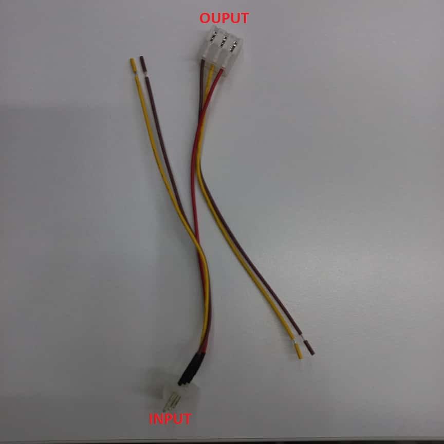HARNESS CABLE](https://docs.antlysis.com/uploads/images/gallery/2025-11/7CGudkRrHSimStcD-pic4.jpg)** **2)** Before we start install device, prepare both a 4-core and a 2-core cable for connecting the device. [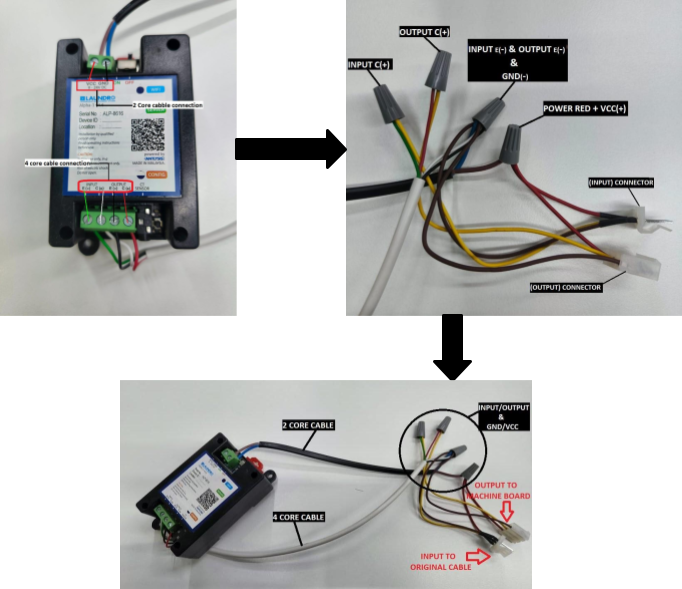INPUT/OUTPUT & GND-/VCC+](https://docs.antlysis.com/uploads/images/gallery/2025-11/d29jHuXal44UY6fX-drawing0.png) **3)** Step by step connection return below. 1. Use a 4-core cable to connect the device’s **INPUT E(-)/C(+)** and **OUTPUT E(-)/C(+)** points. - From the device, take **INPUT E(-)**, **OUTPUT E(-)**, and **GND (-)**, join them together, and connect to the 'harness cable' **INPUT** and **OUTPUT** connections (CHOCLATE ). - From the device, take the **INPUT C(+)** and connect it to the 'harness cable' INPUT (YELLOW ). - From the device, take the **OUTPUT C(+)** and connect it to the 'harness cable' OUTPUT(YELLOW ). - From the device, take the **VCC (+)** and connect it to the red wire on 'the harness cable' (RED ) **4)** Follow the step-by-step connection procedure and connect it to the machine board. [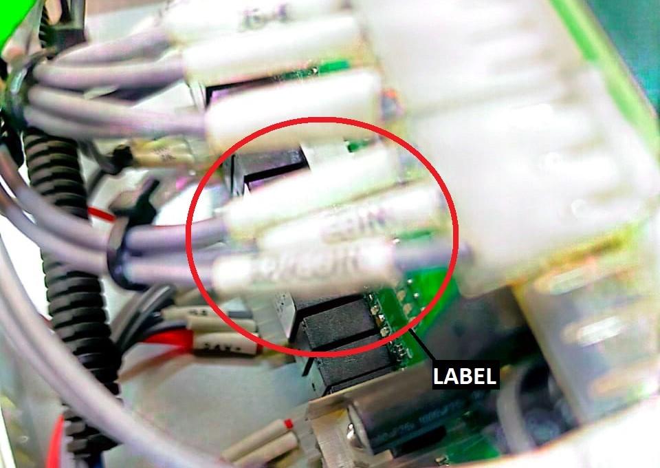](https://docs.antlysis.com/uploads/images/gallery/2025-11/qG1efhHhBJHVnI2M-blue-whale-board-ori.jpg)[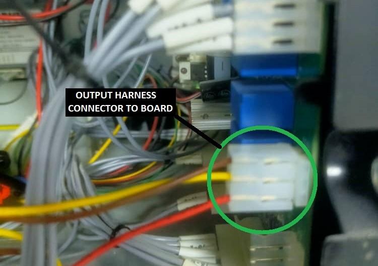](https://docs.antlysis.com/uploads/images/gallery/2025-11/XRRezwX5KX9bRG5Y-blue-whale-harness.jpg) [BLUE WHALE MACHINE BOARD](https://docs.antlysis.com/uploads/images/gallery/2025-11/qG1efhHhBJHVnI2M-blue-whale-board-ori.jpg) - If you are not sure which connector to use, refer to the red-circled label on the cable in the picture. The coin acceptor cable has the same label, so you can match the labels to identify the correct connector on the board. - Find the correct connector by pulling out the cable. Connect it to the harness cable INPUT, then connect the harness cable OUTPUT to the board. #### **WASHER** **[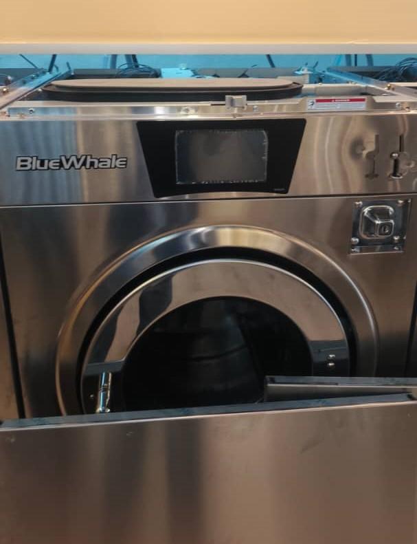](https://docs.antlysis.com/uploads/images/gallery/2025-11/lcJmOfoMJ0b8pqSP-machine1.jpg)** **[BLUE WHALE WASHER](https://docs.antlysis.com/uploads/images/gallery/2025-11/lcJmOfoMJ0b8pqSP-machine1.jpg)** **1)** The new version will use a specific harness cable, and the deice power can take from machine . **[HARNESS CABLE](https://docs.antlysis.com/uploads/images/gallery/2025-11/7CGudkRrHSimStcD-pic4.jpg)** **2)** Before we start install device, prepare both a 4-core and a 2-core cable for connecting the device. [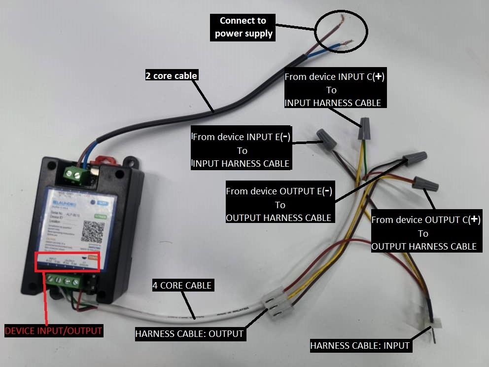Device To Harness Cable Connection](https://docs.antlysis.com/uploads/images/gallery/2025-11/MaA0je0IhqM7CAyh-connection.jpg) **3)** Step by step connection return below. - Connect the device INPUT E(-) (White wire) to the harness cable INPUT (Brown wire). - Connect the device INPUT C(+) (Green wire) to the harness cable INPUT (Yellow wire). - Connect the device OUPUT E(-) (Black wire) to the harness cable OUTPUT (Brown wire). - Connect the device OUTPUT C(+) (Red wire) to the harness cable OUTPUT (Yellow wire). **4)** Follow the step-by-step connection procedure and connect it to the machine board. [](https://docs.antlysis.com/uploads/images/gallery/2025-11/guLKpivxDMStRgTD-washer-1.jpg) [WASHER BOARD ORIGINAL CONECCTION](https://docs.antlysis.com/uploads/images/gallery/2025-11/guLKpivxDMStRgTD-washer-1.jpg) [WASHER BOARD HARNESS CABLE CONNECTION](https://docs.antlysis.com/uploads/images/gallery/2025-11/7gmux4N03tijb5b3-washer-2.jpg) **5**) Find the correct connector by pulling out the cable. Connect it to the harness cable INPUT, then connect the harness cable OUTPUT to the board. **6**) The device will receive power from the machine’s existing power supply. Since there are two power supplies present, use the one that provides 12V. [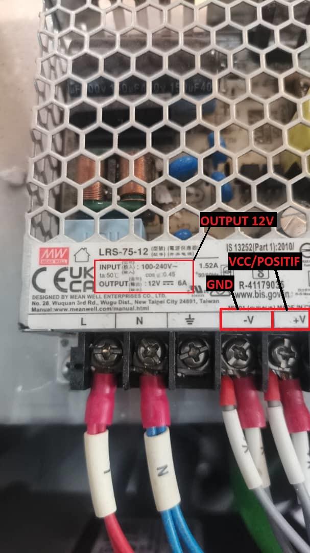Machine Power Supply](https://docs.antlysis.com/uploads/images/gallery/2025-11/4A7qQ7vjW1sMjwTx-power-12v.jpg) **7**) After completing all the connections, power on the machine. The device’s blue indicator light will begin blinking. [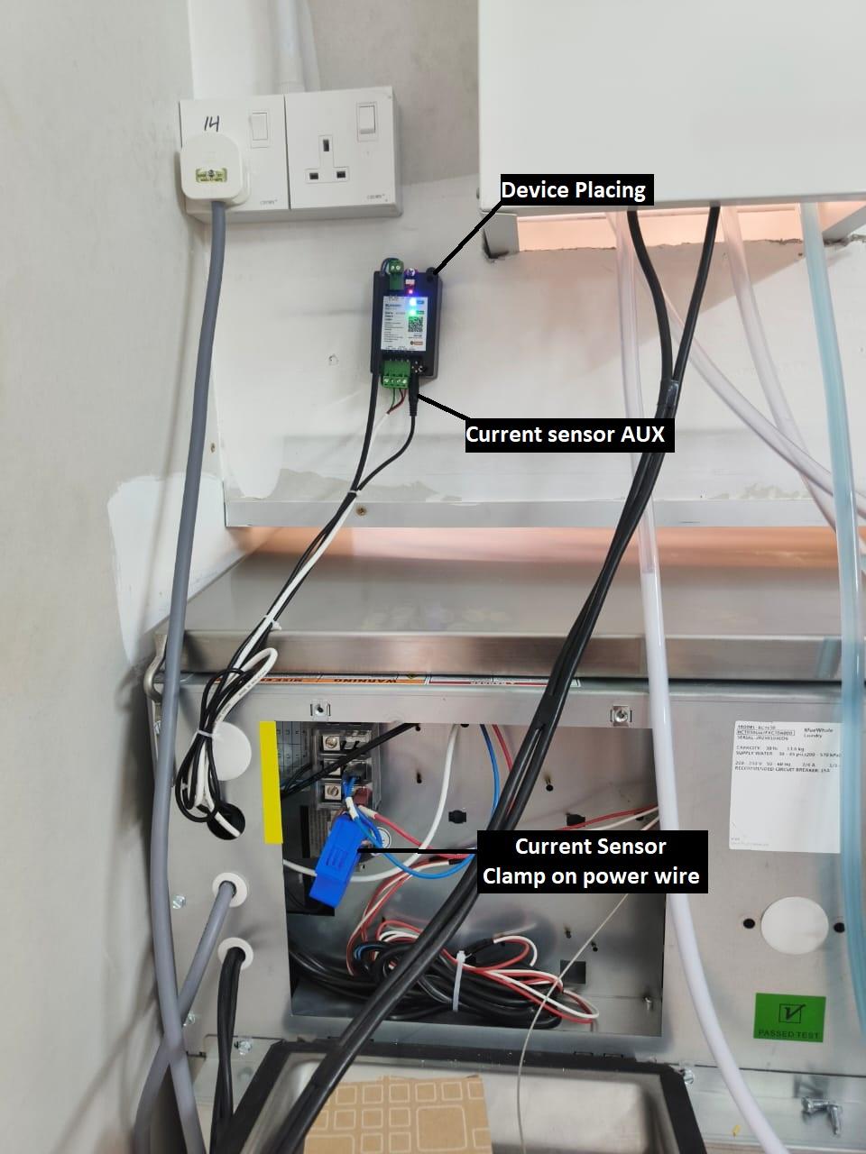CURRENT SENSOR & DEVICE PLACING](https://docs.antlysis.com/uploads/images/gallery/2025-11/CZgBSaxcK0TVUdWN-curennt-sensor.jpg) **8**) You may place the device in the position shown in the picture, or any safer location where it will not be damaged. **9**) Clamp the current sensor onto the machine’s positive power wire, and connect the AUX plug to the device. # WIFI Configuration (ALPHA-1) ##### ***(A) Step-By-Step WIFI Configuration*** 1\. Login to Node-Laundro application ([https://node.thelaundro.com/login](https://node.thelaundro.com/login)) using given username and password. [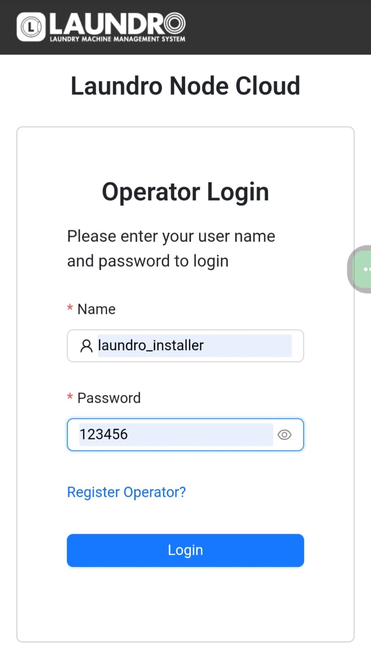Example: Login Page](https://docs.antlysis.com/uploads/images/gallery/2025-08/RpSAYVcUuhkWVZNu-11.jpg) 2\. Search using the outlet name or ID provided, then click on the outlet to view its details. [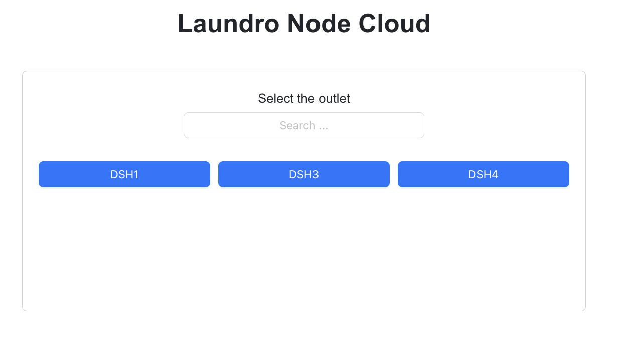](https://docs.antlysis.com/uploads/images/gallery/2025-08/Fdi4DTWZb6s0xvrB-image32.png)[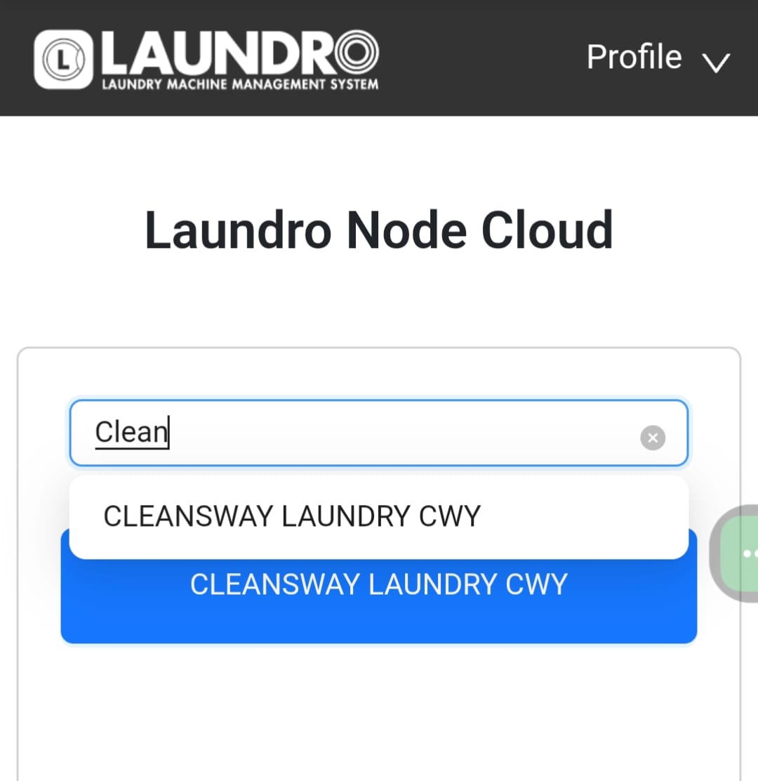](https://docs.antlysis.com/uploads/images/gallery/2025-08/b5PaDawKAZbS0nuD-search-outlet.jpg) [EXAMPLE: Search Outlet Name](https://docs.antlysis.com/uploads/images/gallery/2025-08/b5PaDawKAZbS0nuD-search-outlet.jpg) 3\. By selecting an outlet name, you will be directed to the outlet details page. On this page, verify that all machine counts and details are correct before proceeding to the next step. [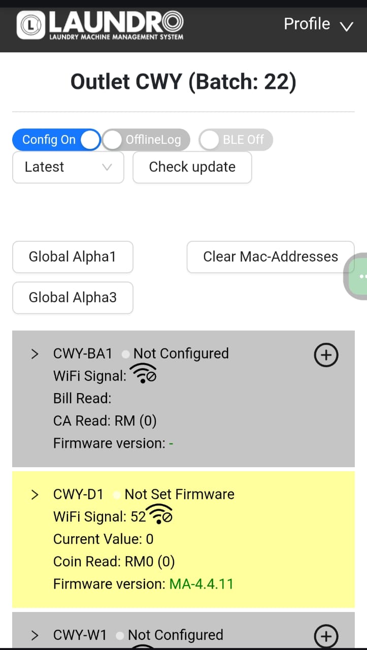](https://docs.antlysis.com/uploads/images/gallery/2025-08/5lOjmOrA1yCa7mtK-outlet-id.jpg) [Example: Outlet Details Page](https://docs.antlysis.com/uploads/images/gallery/2025-08/5lOjmOrA1yCa7mtK-outlet-id.jpg) 4\. Click on enable config mode to allow this outlet to be configurable. [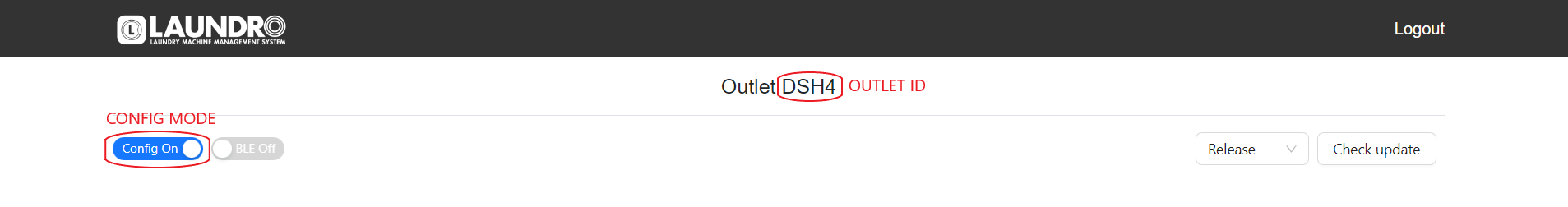Example: On Config Mode](https://docs.antlysis.com/uploads/images/gallery/2025-08/qNC64U6NVWoQvI6L-image71.png) 5\. All machine details will be displayed in grey, indicating they are ready to be configured. Once a device is successfully configured, the background colour will change. [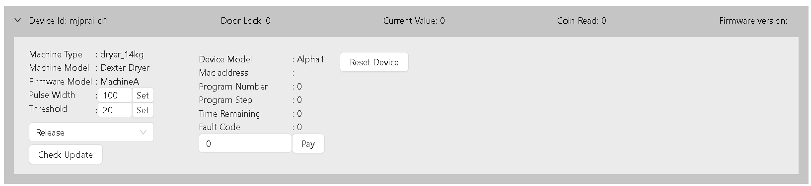Example: Before configure device in grey colour](https://docs.antlysis.com/uploads/images/gallery/2025-08/o0QKtOCJAkW2BXsq-image86.png) 6\. Turn on the switch on the Alpha-1 device and wait for the blue light to start blinking. This indicates that the device is ready for configuration. [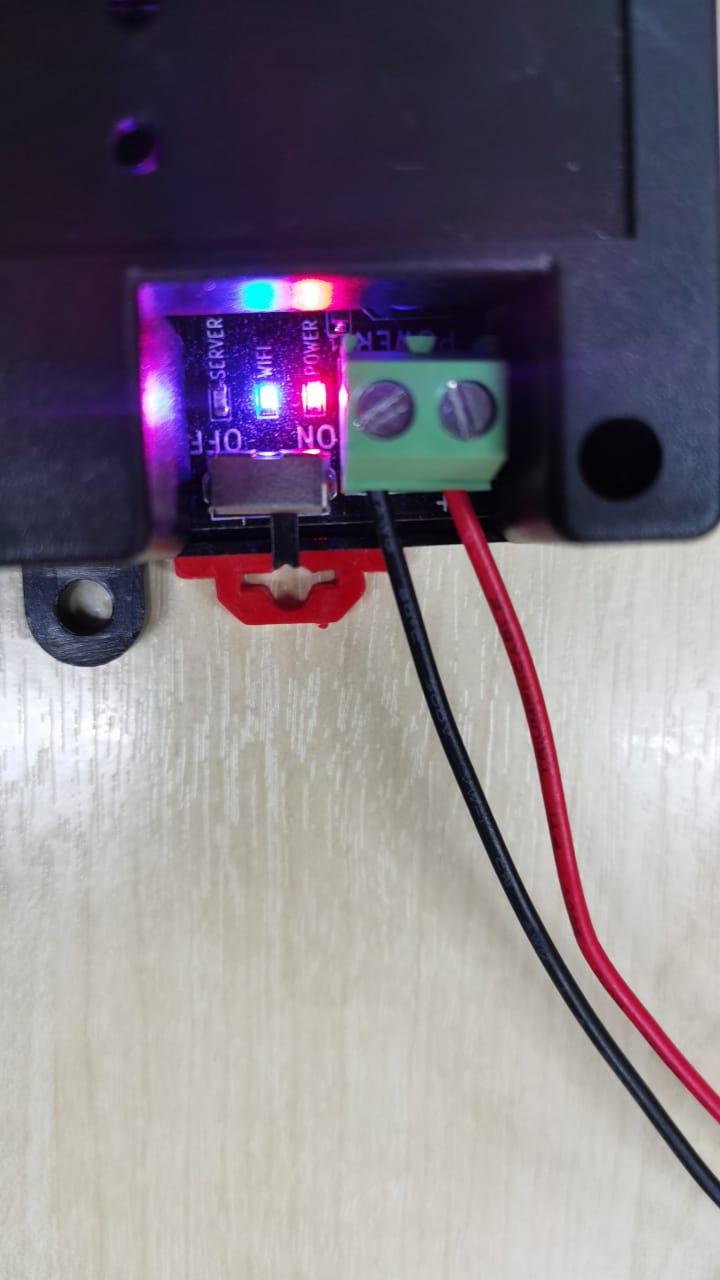Example: Blinking blue light show it’s waiting for connection](https://docs.antlysis.com/uploads/images/gallery/2025-08/oWVIfZhouRmvGIlm-image88.jpg) 7\. Using your mobile phone, open the Wi-Fi settings. You will see the Laundro ID appear, as shown in the picture below. 8\. Connect to newly broadcasted WiFi using default password (123456789) [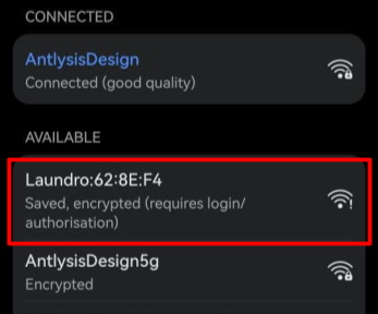Example: Alpha-1 Laundro I'D](https://docs.antlysis.com/uploads/images/gallery/2025-08/dlXjeN9Hg6f4symB-image77.png) 9\. Once connected to the Laundro Wi-Fi, a pop-up will appear directing you to the Wi-Fi Manager page. [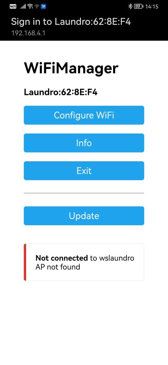Example: WIFI Manger Page](https://docs.antlysis.com/uploads/images/gallery/2025-08/i9vvU1pVExqfujjY-image10.jpg) 💡 **Tip:** 1. If the page doesn’t pop up, simply type **192.168.4.1** into your browser’s address bar, and the Wi-Fi Manager will open. 2. Only for **''SAMSUNG''** Mobile follow the steps below. - Connect your Samsung mobile to the Laundro Wi-Fi. - An **Internet Connection** pop-up will appear. Tap **“Always Connect.”** - Tap the ⚙️**settings icon**. - Select **“Manage Router.”** - The **Wi-Fi Manager** page will open. 10\. Press **‘Configure WIFI’** to open the configuration page. Then, select the correct **SSID**, enter the password, and the **Outlet ID** following in Node Cloud. [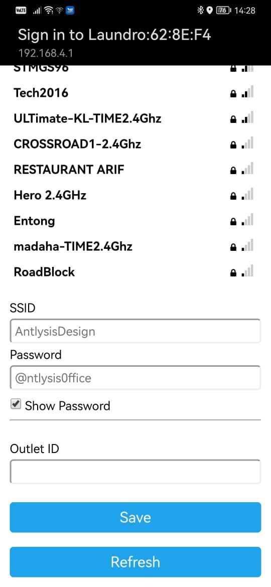Example: WIFI Selection Mode](https://docs.antlysis.com/uploads/images/gallery/2025-08/uJFYMNm6rPsuEfvR-image76.jpg) ⚠️ **Warning:** Ensure that the **Outlet ID** and **Wi-Fi password** are correct. Also, check that there are no spaces before or after the characters before saving. 11\. Once the device is successfully configured to Wi-Fi, the orange and green lights will appear. You can now proceed to the cloud setup. ⚠️ **Warning: Ensure all devices have their WIFI configured before proceeding to the next step.** [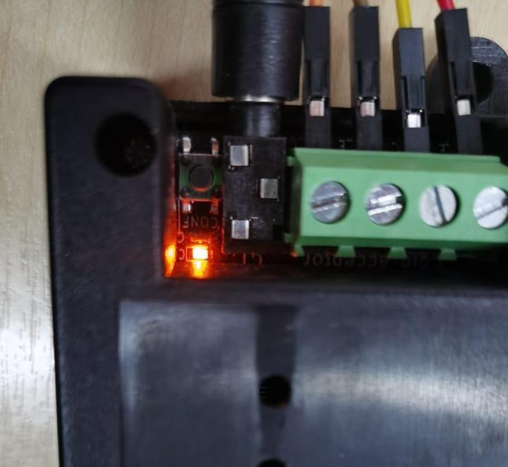](https://docs.antlysis.com/uploads/images/gallery/2025-08/W246ByJSiPUX9k4J-image38.jpg)[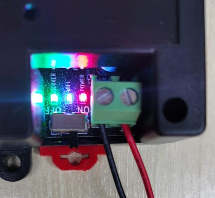](https://docs.antlysis.com/uploads/images/gallery/2025-08/WKp98Lrb9lOCFXF1-image81.jpg) [Example: **Configuration LED and other 3 LEDs (Power, WIFI & Server) are lighted up**](https://docs.antlysis.com/uploads/images/gallery/2025-08/WKp98Lrb9lOCFXF1-image81.jpg) \_\_\_\_\_\_\_\_\_\_\_\_\_\_\_\_\_\_\_\_\_\_\_\_\_\_\_\_\_\_\_\_\_\_\_\_\_\_\_\_\_\_\_\_\_\_\_\_\_\_\_\_\_\_\_\_\_\_\_\_\_\_\_\_\_\_\_\_\_\_\_\_\_\_\_\_\_\_\_\_\_\_\_\_\_\_\_\_\_\_\_\_\_\_\_\_\_\_\_\_\_\_\_\_\_\_\_\_\_\_\_\_\_\_\_\_\_\_\_\_\_\_\_\_\_\_\_\_\_\_\_\_\_\_\_\_\_\_\_\_\_\_\_\_ #### **(B) Steps of Cloud Configuration** **1.** Log back in to the Node-Laundro application **[https://node.thelaundro.com/login ](https://node.thelaundro.com/login)**using the provided username and password. Then, follow the steps in **''**(A) Step-by-Step WiFi Configuration''**** until you reach the **''**Outlet Detail Page**.”** [Example: Outlet Detail Page](https://docs.antlysis.com/uploads/images/gallery/2025-08/5lOjmOrA1yCa7mtK-outlet-id.jpg) 2\. Stay on this page. You will need to press the (+) icon later, but first, continue following the next steps. 3\. On the device, you’ll see a configure button next to the orange light. Press it, and the orange light will begin blinking. [Example: Config Button near Orange LED (Config)](https://docs.antlysis.com/uploads/images/gallery/2025-08/W246ByJSiPUX9k4J-image38.jpg) 4\. Once the orange light starts blinking, you can press the plus **(+)** icon, and the Mac address will pop up. [Example: Plus Icon](https://docs.antlysis.com/uploads/images/gallery/2025-08/Vd8Wp9x41bACyOA2-plus-icon.png) [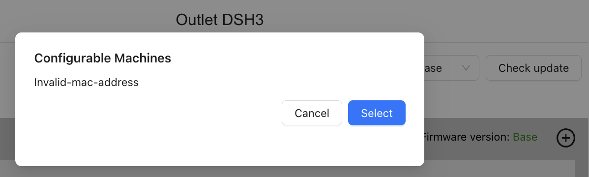](https://docs.antlysis.com/uploads/images/gallery/2025-08/N8kZOaLyyi1G6Uy3-image96.png)[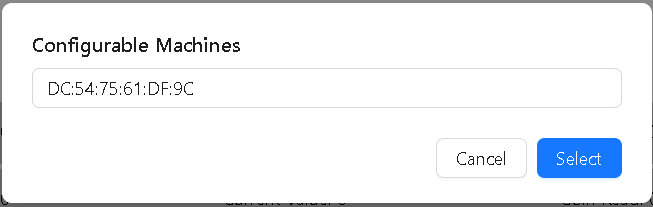](https://docs.antlysis.com/uploads/images/gallery/2025-08/AmEBhJAQig8YgkKO-image7.png)[Example: Mac address Pop-up](https://docs.antlysis.com/uploads/images/gallery/2025-08/N8kZOaLyyi1G6Uy3-image96.png) 5\. Once the MAC address pops up, click *Select*. 6\. After selecting the correct MAC address, the section you configured from grey will turn yellow. [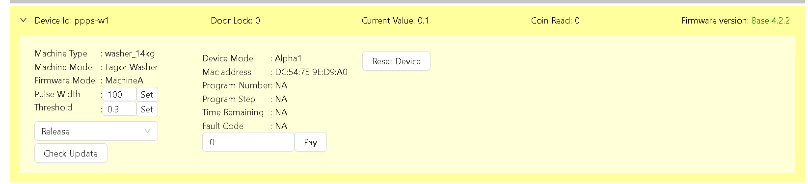Example: Section from Grey turn to Yellow](https://docs.antlysis.com/uploads/images/gallery/2025-08/wLJXogOp0imUkxjT-image41.png) 7\. Select the ***latest*** option, then click ***Check Update***. The latest version will appear, and you can click ***Update*** **[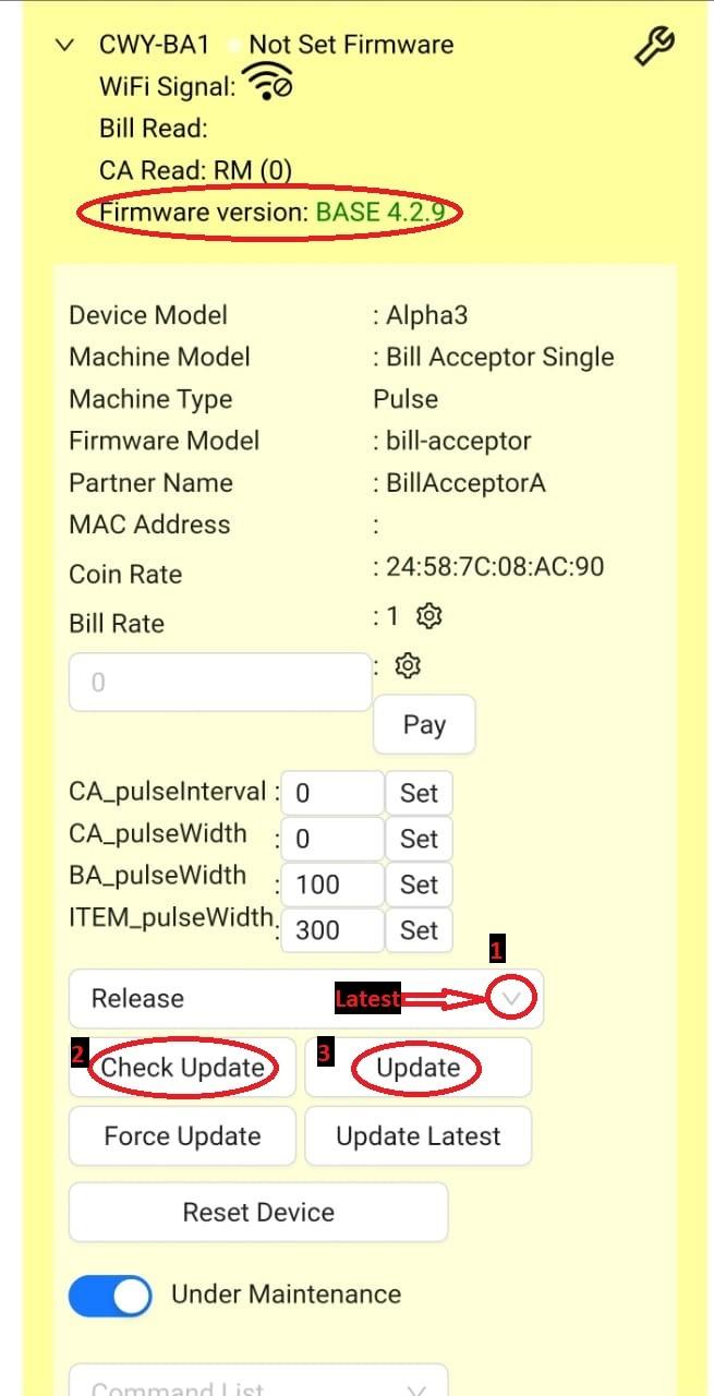Example: Step by step check update](https://docs.antlysis.com/uploads/images/gallery/2025-08/FLbRkuJVVZmWzYR4-chek-update-2.jpg)**  **Quality Note:** If configuration is done in the wrong section: 1. 1. In the Cloud App, click **Reset Device**. 2. On the device, long press the **Configure** button until the orange light appears. 3. Select the correct machine ID and repeat the step with the **Plus (+) Icon**. [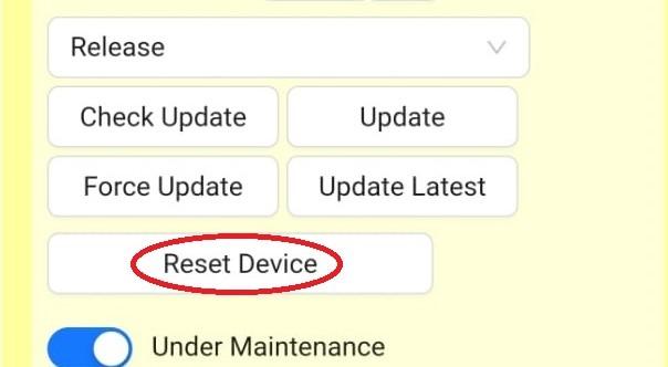Example: Reset Device on app](https://docs.antlysis.com/uploads/images/gallery/2025-08/Jj6t7dDWbZwUkYgF-reset-device.jpg) 8\. Once the update is successful, the section will turn blue colour. You can then proceed with testing. [Example: Blue Colour Ready For Testing](https://docs.antlysis.com/uploads/images/gallery/2025-08/kuFuUlKzK7aqsn84-image8.png) 9\. When the machine’s ‘Current Value’ exceeds the ‘Threshold’ value, the machine status will turn green. [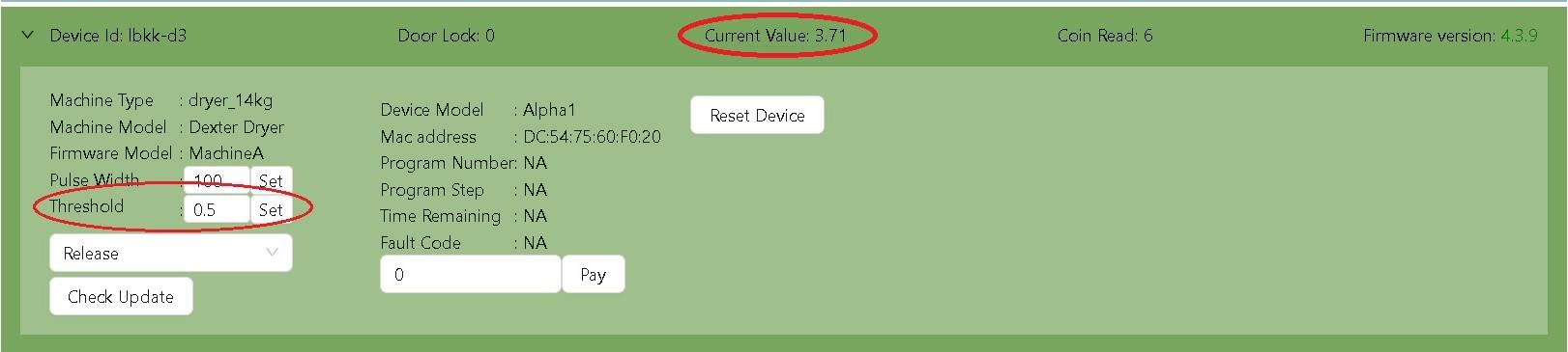Example: Current Value increase Threshold Value ](https://docs.antlysis.com/uploads/images/gallery/2025-08/xEWtyT4k8vrhQSkO-testing.jpg) ##### (C) Status on Node Machines are displayed with 6 types of status. 1. Grey - Not configured 2. Yellow - Pending Update 3. Blue - Idle status 4. Green - Running Status 5. Red - Offline Status 6. Bright red - Abnormal Status [](https://docs.antlysis.com/uploads/images/gallery/2025-08/o0QKtOCJAkW2BXsq-image86.png) [](https://docs.antlysis.com/uploads/images/gallery/2025-08/wLJXogOp0imUkxjT-image41.png) [](https://docs.antlysis.com/uploads/images/gallery/2025-08/kuFuUlKzK7aqsn84-image8.png) [](https://docs.antlysis.com/uploads/images/gallery/2025-08/eFvYj6iyYmW0oY7Q-image12.png) [](https://docs.antlysis.com/uploads/images/gallery/2025-08/9m9lHZxz9L3dsEOe-image75.png) [](https://docs.antlysis.com/uploads/images/gallery/2025-08/zDjROi7Mz2BSaVFy-image21.png) # Electrolux - Installation # Alpha1 v4 to v5 Firmware Migration Procedure This document provides the technical steps required to migrate device partitions and upgrade to the latest production firmware. ## 1. Initial Firmware Preparation - **Navigate** to the target device within the Node Cloud dashboard. - **Select "Migration"** from the Release dropdown menu. - **Click "Force Update"** and wait for the device to reboot. - **Confirm** that the firmware version is now **XX-0.10.10**. [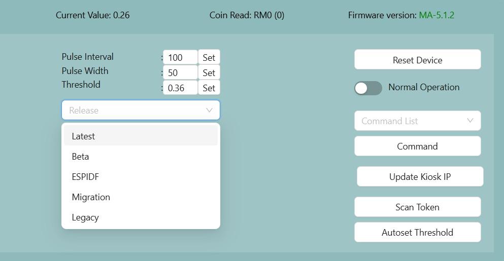](https://docs.antlysis.com/uploads/images/gallery/2026-01/TIndrxdiSSJxSpTW-whatsapp-image-2026-01-05-at-9-27-43-am.jpeg) ## 2. Pre-Migration Validation Execute the **Fetch Partition Status** command from the conmmand list to determine the migration state.| Response | Action |
|---|---|
| `PartitionMigration_Uninitiated` | Proceed to Migration |
| `PartitionMigration_NotStarted` | Proceed to Migration |
| `PartitionMigration_Completed` | Migration not needed; skip to Phase 4 |
| `PartitionMigration_ErrorReadingStatus` | **Stop** and report issue |
| `PartitionMigration_Failed` | **Stop** and report issue |
\[!CAUTION\] If `PartitionReformat_Fail` or `PartitionReformat_CriticalFail` is displayed, do not proceed. Report the failure immediately!
## 4. Final Firmware Update - Select **Latest** in the Release dropdown menu. - Click **Check Update**. - When prompted with **"5.X.X available"**, click **Update**. - **Verification:** Following the reboot, ensure the firmware version is updated to **XX-5.X.X**.If still intent to use legacy, use the legacy release (firmware version will be 4.4.11)
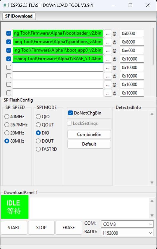
# Procedure to Flash Alpha device #### **Prerequisites** Before starting, ensure you have the following: - Download Flashing tool and latest firmware here -> [Flashing Tool.zip](https://docs.antlysis.com/attachments/29) - Windows laptop/pc (recommended) - microUSB cable - Cytron USB-UART Converter UC00C (shown below) [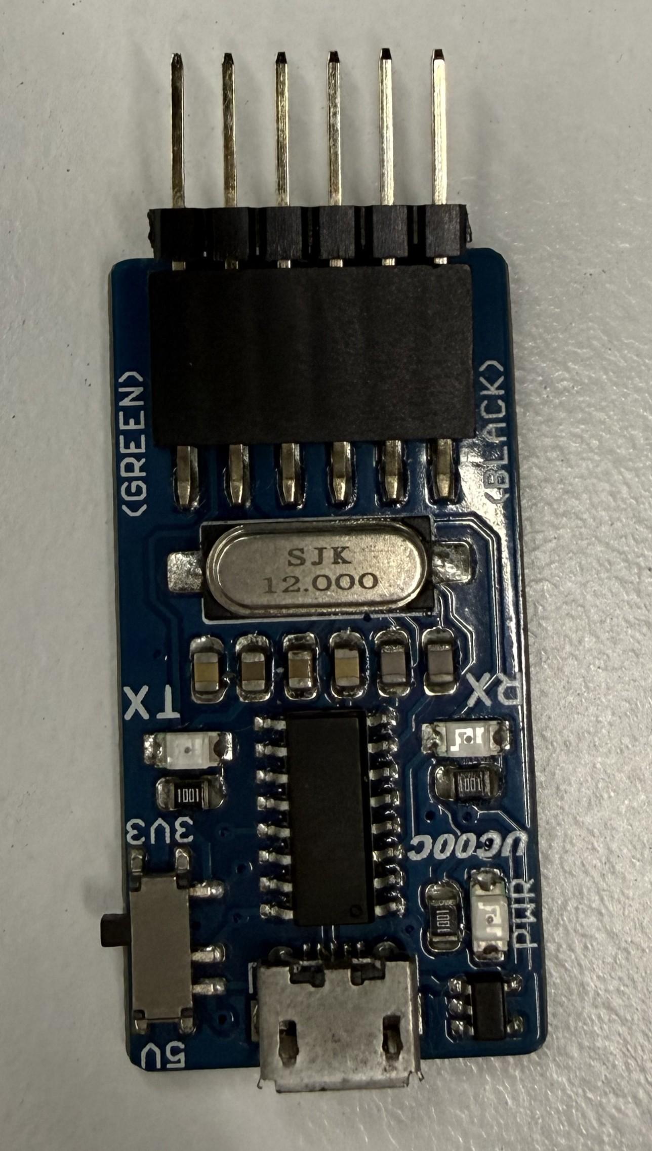](https://docs.antlysis.com/uploads/images/gallery/2026-01/vudm3cgJ1eHyXV2x-img-9109.jpg) --- #### **Flashing Procedure** 1. The programmer pins must be exposed via male headers at a 2.54mm pitch 2. **Pin Order:** Ensure the pins are arranged in this specific sequence: 1. DTR 2. RX 3. TX 4. 3.3V 5. RTS 6. GND 3. Insert the programmer into the flashing female port of the board, matching the pin names **except for TX and RX**, which are typically swapped. 4. Tilt the programmer at an angle to ensure a solid electrical connection with the port. [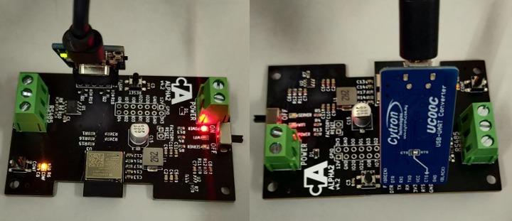](https://docs.antlysis.com/uploads/images/gallery/2026-01/86PjpZ6LmlnpB4TZ-whatsapp-image-2026-01-14-at-12-17-09-pm.jpeg) 5. Open the downloaded **Espressif Flash Download Tool **(Flashing Tool -> flash\_download\_tool\_3.9.4). 6. Upon opening the software, select the following settings: - **Chip Type:** ESP32-C3 - **WorkMode:** Develop (for single board) or Factory (for multiple boards) - **LoadMode:** UART [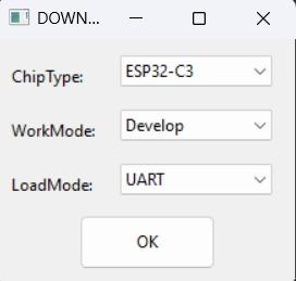](https://docs.antlysis.com/uploads/images/gallery/2026-01/J1WwI9Ezvsd2r7y4-whatsapp-image-2026-01-14-at-12-22-27-pm.jpeg) 7. Set the file paths at the following addresses:| **File Name** | **Memory Address (Offset)** |
| `bootloader_v2.bin` | 0x0000 |
| `partitions_v2.bin` | 0x8000 |
| `boot_app0_v2.bin` | 0xe000 |
| `AlphaX_BASE_x.x.x.bin` | 0x10000 |
The files can be located at: Flashing Tool -> Firmware -> (select device model eg: Alpha1)
PLEASE USE THE LATEST FILES PROVIDED IN THE ATTACHED FILE ABOVE
8. Configure the **SPI Flash Config** section as follows: - **SPI SPEED:** 80MHz - **SPI MODE:** DIO - **Baud Rate:** 921600 9. The flashing process: - For Single Boards: - Select the appropriate **COM port** - Click **"START"** to begin. - Monitor the progress bar as the upload proceeds. - For Multiple Boards (Factory Mode) - Uncheck **"LockSettings"** to modify configurations. - Assign the correct **COM port** for each attached programmer. - Re-check **"LockSettings"** to secure the configuration. - Click **"START ALL"** to flash all boards simultaneously.NOTE: It is recommended to ERASE the board first before re-flashing it. This can be done by pressing ERASE in the flashing tool before flashing.
[](https://docs.antlysis.com/uploads/images/gallery/2026-01/Acb59lvCFK8HT0dR-whatsapp-image-2026-01-14-at-12-23-33-pm.jpeg) --- #### **Verification** Once the upload is complete, look for the following indicator on the board: - The **blue, green, and yellow LEDs** will flash **twice** to signify a successful firmware upload - The **blue** led will start blinking continuously indicating that device is ready to be setup and configured # Alpha1 Latest Firmware Overview **Latest Version:** 5.1.4 **Platform:** ESP32-C3 **Framework:** ESP-IDF ## Overview Alpha1 v5 is an IoT firmware solution designed primarily for the intelligent management of commercial washers and dryers in laundromats, alongside general vending and payment system integration. Built on the ESP32 platform using the ESP-IDF framework, this firmware provides comprehensive connectivity, monitoring, and control capabilities tailored for various laundromat machine types and stacked configurations. ## Features - **Multi-Environment Support**: Configurable for different machine types (BASE, MachineA, MachineB, MachineC, StackA, KioskCAA, GasSensorA) - **Real-time Monitoring**: Current sensing, pulse detection, and status reporting - **Secure Connectivity**: WiFi management with captive portal and MQTT communication - **Payment Processing**: Support for coin and electronic payment systems - **Remote Management**: OTA updates, configuration management, and remote diagnostics - **Data Persistence**: Critical data backup and recovery with NVS storage and LittleFS file system - **Web Interface**: Built-in web server with responsive UI (embedded HTML/JS/CSS) for device configuration - **Auto-calibration**: Intelligent threshold calibration for optimal performance ## Architecture ### Core Components #### Main Application (`src/main.c`) The main application orchestrates all system components and provides: - Environment-specific machine type selection - Global variable management - System initialization and task coordination - Event handling and queue management #### Configuration Management (`src/Alpha1_configurations.h`) Centralized configuration system defining: - Device configuration structures - Machine type definitions - Queue message enumerations - Auto-threshold calibration parameters ### Machine Types #### 1. BASE Environment - **Purpose**: Factory default firmware flashed onto every new device before deployment - **Features**: WiFi connectivity, OTA update capability, and cloud communication. No machine-specific logic. Once the device is registered in the Node Cloud platform, the operator selects the machine type and the correct firmware is pushed to the device over-the-air. - **Build Flag**: `-D BASE` #### 2. MachineA / MachineB / MachineC Environments (`src/Machines/MachineX.h/.c`) - **Build Flags**: `-D MACHINE_A`, `-D MACHINE_B`, `-D MACHINE_C` - **MachineA** — Standard coin-op washer or dryer. Uses CT current sensing to detect running/idle cycles and a timer-based pulse reader to count coin drops. Lock data records both the start and end of each cycle. Supports local kiosk MQTT and auto-threshold calibration. - **MachineB** — Detergent dispensers, water vending machines, and similar coin/bill-operated product dispensing equipment. No current sensing or cycle tracking. Counts bill/token pulses using a timer-based reader. Transaction completion is determined by an inactivity timeout (lock-check counter) rather than a CT sensor transition. - **MachineC** — Commercial washer or dryer using a hardware rising-edge GPIO interrupt for coin pulse detection instead of a timer. CT current sensing and lock data work the same as MachineA. Includes a noise filter on the pulse reader during active cycles and supports local kiosk MQTT. #### 3. StackA Environment (`src/Machines/StackA.h/.c`) - **Purpose**: Advanced stacked machine system (shared motherboard) - **Features**: - Multiple payment methods (coin, epay, cash advance) - Enhanced current monitoring - Extended payment processing capabilities - Advanced status reporting - **Build Flag**: `-D STACK_A` #### 4. KioskCAA Environment (`src/Machines/KioskCAA.h/.c`) - **Purpose**: Centralized kiosk management integration - **Features**: Kiosk-based payment routing and control - **Build Flag**: `-D KIOSKCA_A` #### 5. GasSensorA Environment (`src/Sensors/GasSensorA.h/.c`) - **Purpose**: Dryer cycle monitoring via gas tong pulse detection - **Features**: Connects to the gas tong (burner assembly) signal line of gas-powered dryers. Counts pulses each time the burner fires to track dryer cycle runs. Tracks both a current pulse count and a lifetime cumulative total, reported periodically to the cloud. No payment processing, no current sensing. - **Build Flag**: `-D GASSENSOR_A` ### Managed Components #### Common Core Component - **`alpha_common`**: Shared operational logic, unified commands, UI templates, and network abstractions utilized across all machine types. #### Connectivity Components - **`wifi_app`**: WiFi connection management and captive portal - **`mqtt_app`**: MQTT client for cloud communication - **`wm_app`**: WiFi Manager for network configuration - **`sntp_app`**: Network time synchronization #### Data Management Components - **`nvs_app`**: Non-volatile storage management - **`criticalData_app`**: Critical data backup and recovery - **`ota_app`**: Over-the-air firmware updates #### Hardware Interface Components - **`pulse_app`**: Pulse detection and counting - **`ct_app`**: Current transformer interface - **`ui_app`**: User interface and LED management ## File Structure ``` src/ ├── main.c # Main application entry point ├── Alpha1_configurations.h # Global configuration definitions ├── Machines/ │ ├── MachineA.h/.c # MachineA implementation │ └── StackA.h/.c # StackA implementation ├── Sensors/ │ └── GasSensorA.h/.c # Gas sensor interface └── webpage/ ├── index.html # Web interface HTML ├── code.js # Client-side JavaScript └── style.css # Styling ``` ## Build Environments ### Prerequisites - PlatformIO - ESP-IDF framework - ESP32-C3 development board ### Environment Configuration #### BASE Environment ```bash pio run -e BASE ``` - Minimal feature set - Basic monitoring capabilities #### Machine Environments (MachineA, MachineB, MachineC) ```bash pio run -e MachineA # or MachineB, MachineC ``` - MachineA/C: CT current sensing, coin pulse detection, cycle-based lock data - MachineB: Bill/token pulse counting for detergent vending, water vending, and similar dispensing machines, inactivity-based transaction completion #### StackA Environment ```bash pio run -e StackA ``` - Dual-payment system - Support for coin, epay, and cash advance #### Specialized Environments ```bash pio run -e KioskCAA pio run -e GasSensorA ``` - KioskCAA: Central payment routing to machines on the floor - GasSensorA: Dryer cycle counting via gas tong pulse detection ### Build Configuration The firmware uses environment-specific build flags defined in `platformio.ini`: ```ini [env:BASE] build_flags = ... -D BASE [env:MachineA] build_flags = ... -D MACHINE_A [env:StackA] build_flags = ... -D STACK_A ``` #### Custom Firmware Extraction A custom Python script (`copyFirmware.py`) is embedded in the build process via `extra_scripts`. It copies the resulting binaries into release folders automatically. #### Partition Setup The project defines custom board partitions using `alphaX_partitions.csv`, efficiently structuring the ESP32-C3 flash for Application, NVS, LittleFS, and OTA logic. ## Hardware Requirements - **MCU**: ESP32-C3 DevKit M-1 - **Flash**: Minimum 4MB - **RAM**: 400KB SRAM - **Connectivity**: WiFi 802.11 b/g/n - **ADC**: For current sensing - **GPIO**: For pulse detection and LED indicators ### Pin Configuration - Current sensing via ADC - Pulse input detection - Status LEDs (WiFi, MQTT, Config) - Configuration and reset buttons ## Installation 1. **Clone the repository:** ```bash git clone https://github.com/Antlysis/Alpha1-v5.git cd Alpha1-v5 ``` 2. **Install dependencies:** ```bash pio pkg install ``` 3. **Build for specific environment:** ```bash # For MachineA pio run -e MachineA # For StackA pio run -e StackA # For BASE pio run -e BASE ``` 4. **Upload firmware:** ```bash pio run -e MachineA -t upload ``` ## Configuration ### Initial Setup 1. Power on the device 2. Connect to the WiFi access point `Laundro:XX:XX:XX` 3. Navigate to `192.168.4.1` in a web browser if configuration portal does not open automatically 4. Configure WiFi credentials and outlet parameters ### MQTT Configuration - **Broker**: Configurable via web interface - **Topics**: Auto-generated based on device MAC address - **QoS**: Configurable per message type - **Last Will**: Automatic disconnect detection ### Device Parameters - **Outlet ID**: Unique identifier for the machine - **Device IDs**: Primary and secondary device identifiers - **Pulse Configuration**: Width and interval settings - **Threshold Values**: Current detection thresholds ## API Reference ### Machine Interface Functions #### MachineA/StackA Common Functions ```c void machine_begin(Alpha1_t *conf); // Initialize machine void machine_status(char *status, criticalData_t *lockData, char *time); // Get status int machine_pay(char* payload); // Process payment bool machine_command(char *payload, int length, char *response); // Execute command void machine_updateConfig(void); // Update configuration ``` ### MQTT Topics Structure ```| Supported Chipset | Notes |
|---|---|
| ESP32-C3 | Tested & Fully supported |