Alpha-1v4 Manual
- ALPHA-1 v4 Technical Overview
- Dexter - Installation
- LG - Installation
- Speed Queen v1- Installation
- IPSO - Installation
- Go World - Installation
- Fargo - Installation
- Blue Whale - Installation
- WIFI Configuration (ALPHA-1)
- Electrolux - Installation
- Alpha1 v4 to v5 Firmware Migration Procedure
- Procedure to Flash Alpha device
- Alpha1 Latest Firmware Overview
- Alpha1 General Overview
ALPHA-1 v4 Technical Overview
System Description for Version 4
A typical coin acceptor sends a signal to a machine through a pulse. The number of pulses will indicate the value of the coin inserted. The pulse signal has two properties:
-
Pulse Width - The length of the pulse
-
Pulse Interval - The length between pulses
Coin rate is the number of pulses for RM1.
Eg.
-
RM0.5 produces 5 pulses - Coin rate = 10
-
RM0.5 produces 1 pulse - Coin rate = 2
-
RM1 or 1 token produces 1 pulse - Coin rate = 1

Our Alpha1 device is placed in between the coin acceptor and machine. The Alpha1 device has 3 main functions:
-
It allows the signal to pass through from the input to the output.
-
It reads the pulse based on the pulse width. (Coin Read)
-
It outputs pulses from the cloud based on the pulse interval. (Cloud Pay)

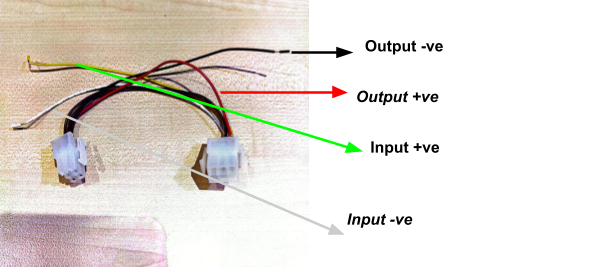
Alpha-1 version 4.3 is an upgrade which aims to ease the installation process. The diagram below shows an overview of what its wire connection looks like. There’s primarily 2 major update in this version:
-
Device is connected directly to cloud
-
Smaller in size to allow easier handling
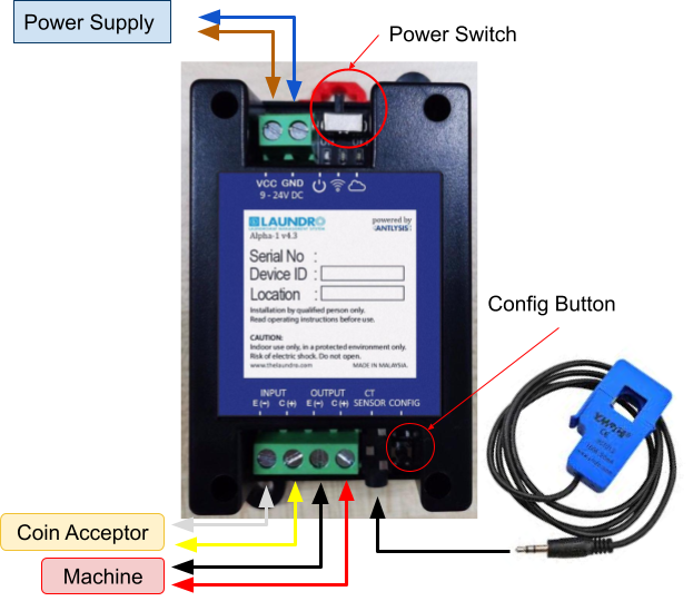
Figure 1: Alpha-1 version 4.3 Connection Overview
________________________________________________________________________________________________________________________________________________
Equipment and Material Required
1. 4 cores cables
2. 2 cores power cable
- 23/0.15 x 2 cores (~2.0A)
- 42/0.15 x 2 cores (~6.0A)
3. Test Pen ( 5mm Standard Tip)
4. Self-adjusting Wire stripper
5. Hexagon Socket screwdriver bit, 8 mm
- Dexter
- Speed Queen
6. Hexagon Socket screwdriver bit, 7 mm
- Lavamac
7. Hexagon Socket screwdriver bit, 10 mm
-
IPSO
8. Torx Screwdriver Bit, T30
- Electrolux
9. Torx Screwdriver Bit, T20 With Hole
- LG
- Dexter
10. Torx Screwdriver Bit, T10
- Dexter
Dexter - Installation
Alpha-1 Placement on Machine
Example: Dexter Stacked Washer Dryer


Example: Dexter Stacked Dryer

________________________________________________________________________________________________________________________________________________
Connection from Harnnes to ALPHA-1
(A) Alpha-1 connection ''Input'' ''Output''

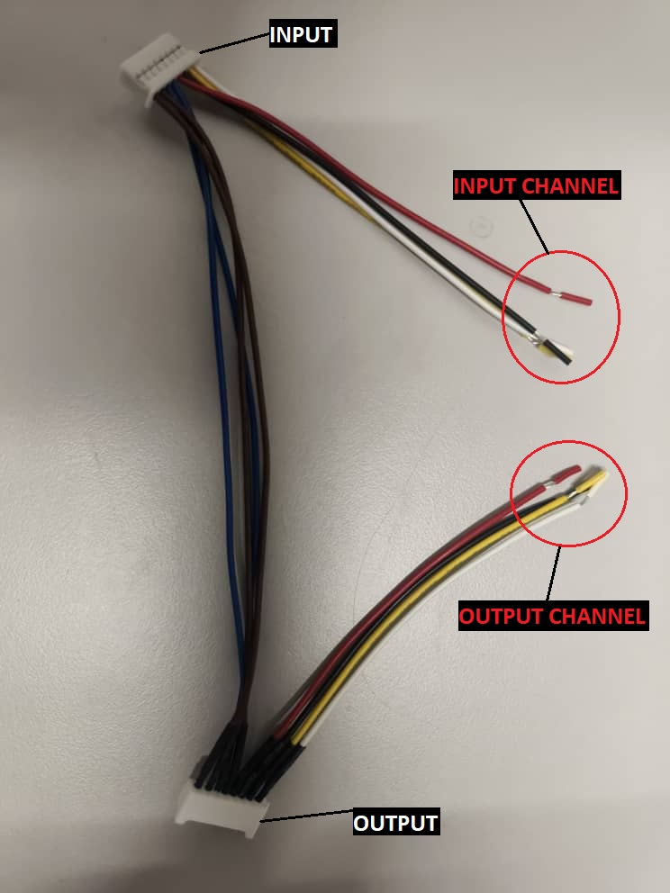
1. device has input and output connections labeled (IN: +, –) and (OUT: +, –). Use a 4-core cable to connect the input (+/–) and output (+/–) terminals.
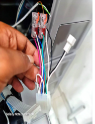
(B) Harness connection on machine ''Dexter''
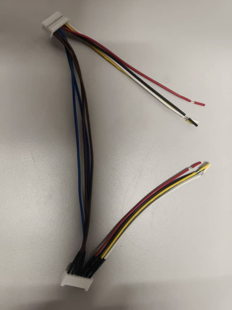
2. This harness cable is connected to the machine’s coin acceptor. It has two channels: the first channel uses yellow and white wires, and the second channel uses red and black wires.
3. Try using the first channel (yellow/white) to connect the input and output on the harness using a 4-core cable from the device."
4. Begin testing. If there is no response, check the input and output connections and the device. If all connections are correct but the issue remains, try switch to the second channel.
LG - Installation
Alpha-1 Placement on Machine
Example: LG Stacked Washer Dryer
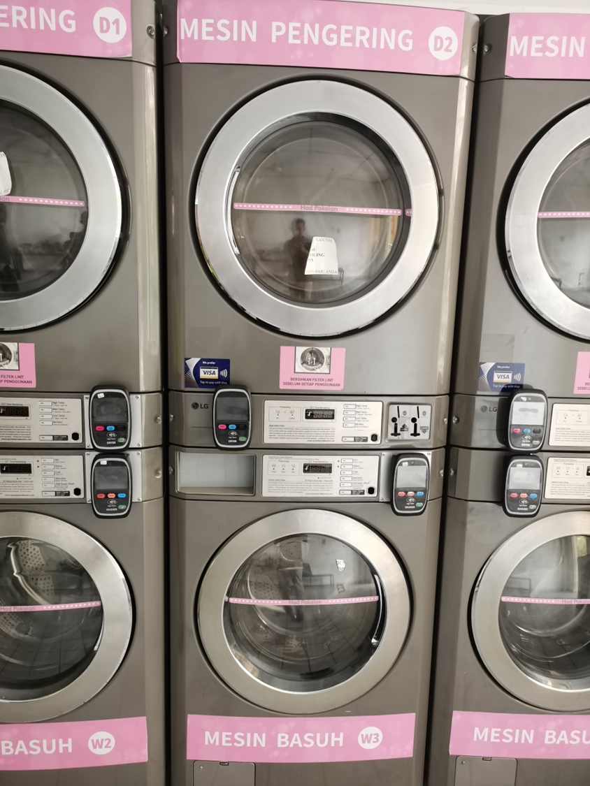 STACK DRYER/WASHER
Be cautious before installation ⚠️
-
No pinch and wire for the main board while installing.
-
Turn off the machine electricity while during installation.
Device Placement


Washer Placement Dryer Placement
________________________________________________________________________________________________________________________________________________
Connection from Harness to ALPHA-1
(A) Alpha-1 connection ''Input'' ''Output''
1) device has input and output connections labelled (IN: +, –) and (OUT: +, –). Use a 4-core cable to connect the input (+/–) and output (+/–) terminals.
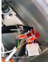
(B) Harness connection on machine ''LG MACHINE''
2) This harness cable is connected to the machine’s coin acceptor. It has two channels: the first channel uses yellow and white wires, and the second channel uses red and black wires.
3) Try using the first channel (yellow/white) to connect the input and output on the harness using a 4-core cable from the device."
4) Begin testing. If there is no response, check the input and output connections and the device. If all connections are correct but the issue remains, try switch to the second channel.
________________________________________________________________________________________________________________________________________________
LG Cashless Machine
Be cautious before installation
-
No pinch and wire for the main board while installing.
-
Turn off the machine electricity while during installation.
1) Remove the screw at the marked position shown in the picture.
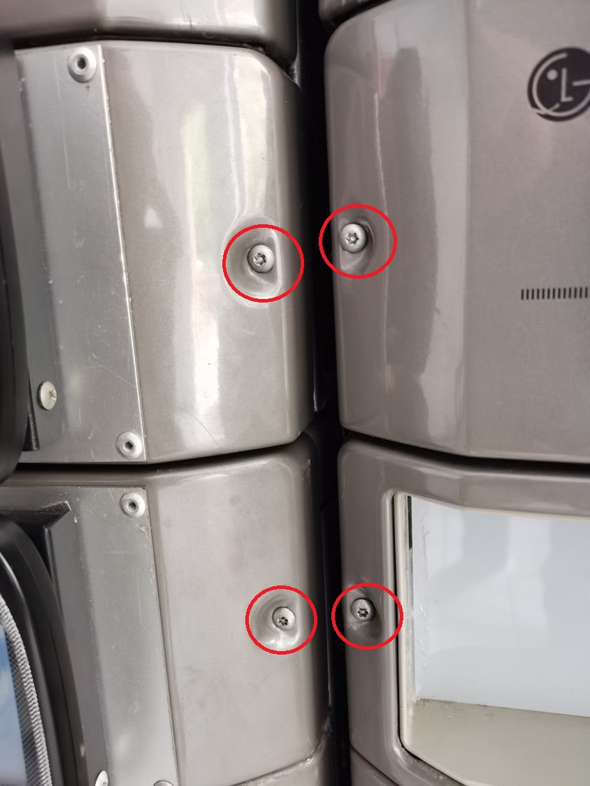 T20 SCREW
2) After opening the board casing, the board connections will be visible. Remove the connectors and store the board casing safely.
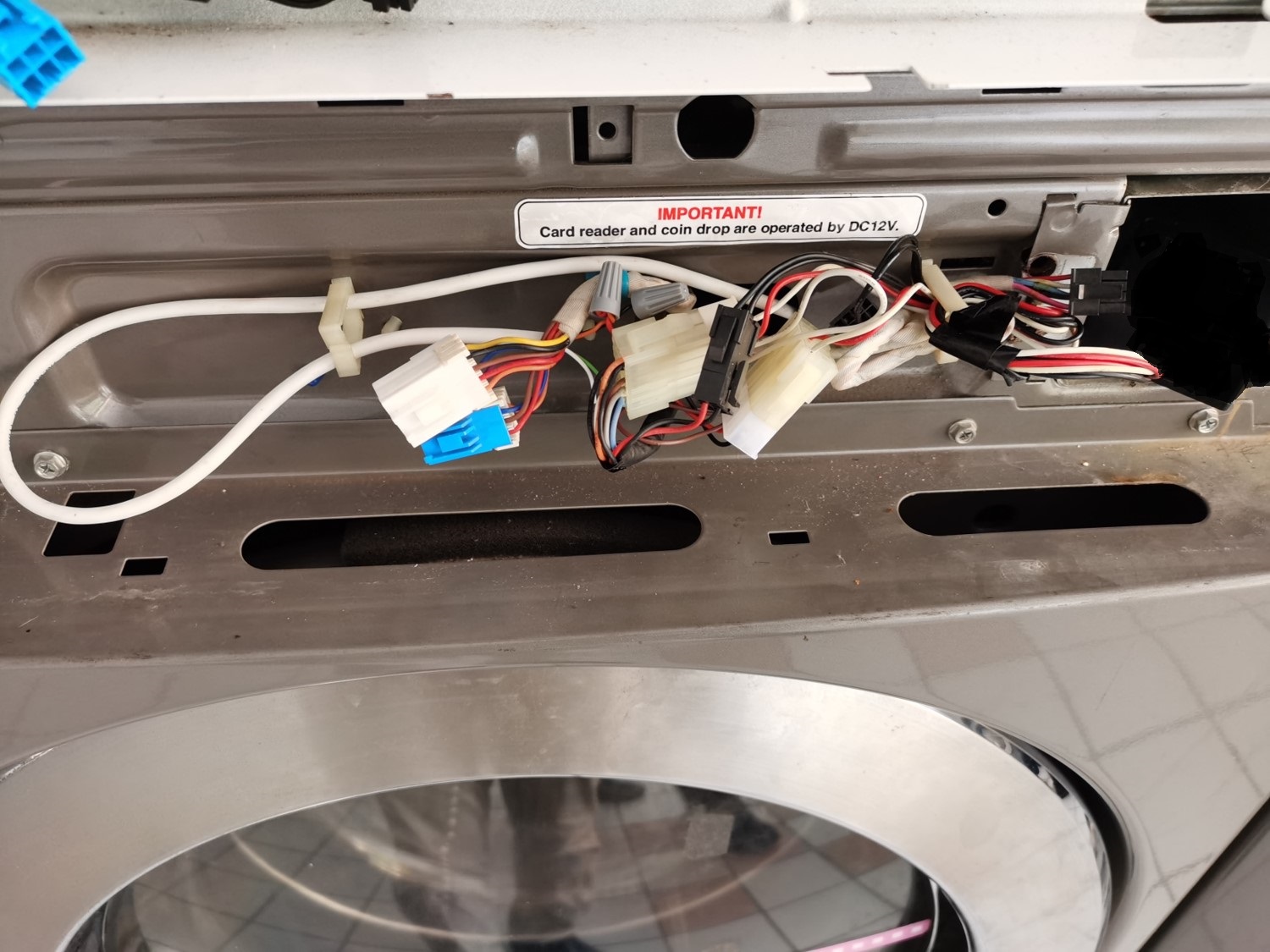 ORIGINAL LG CONNECTION
3) LG Cashless system uses a specific harness cable.
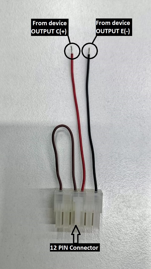
LG CASHLESS HARNESS CABLE
4) The machine connection has a 12-pin connector. Remove it and connect it to the 12-pin harness cable connector.
5) Use a 4-core alarm cable from device, but only the red and black wires are required. Connect these two wires to the harness cable.
Device Connection
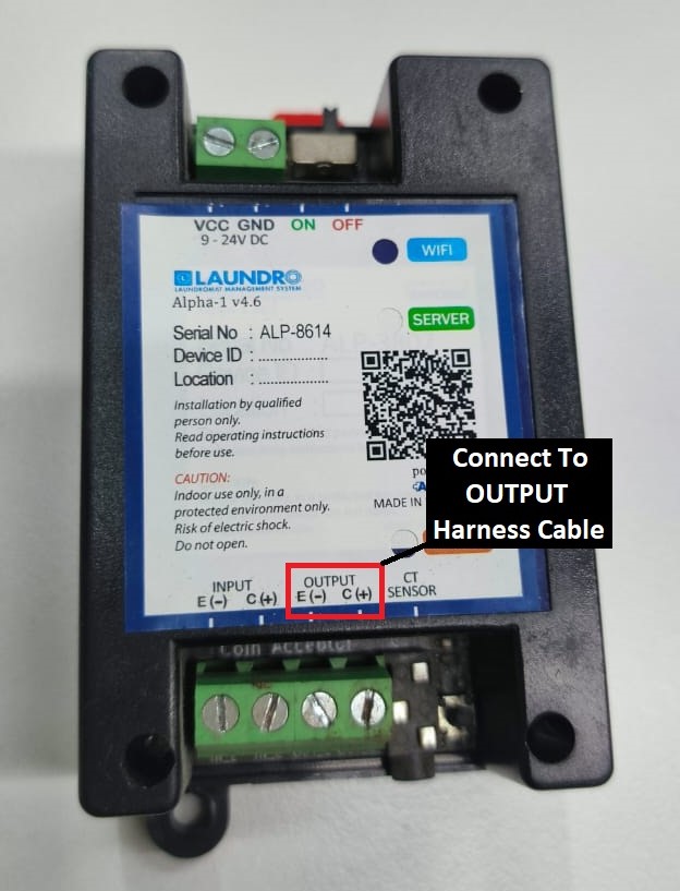
6) Using a 4-core cable, connect it to the device OUTPUT terminals E (–) and C (+).
Connection from device to harness cable
-
From device E ( - ) <> Harness cable ''BLACK''
-
From device C (+) <> Harness cable ''RED''
Speed Queen v1- Installation
Speed Queen Single Washer & Stack washer / Dryer
Type off Speed Queen Machine
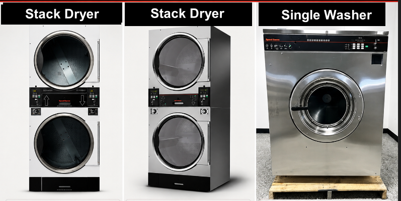

“Types of installation for Speed Queen machines”
Cashless Installation- Speed Queen Stack Washer/Dryer STGNCASP116TW01
☞ Cashless connection for E-payment transactions only, suitable for machines without a coin acceptor or machines with a coin acceptor where token capture is not required.
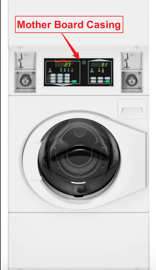
1) Open the motherboard casing using the specific machine key provided.
2) Pull the wires from the front to the back of the machine, where you will be placing the Alpha-1 device.
👉 For the Speed Queen machine, it is recommended to use 1.5 mm thick cables for the OUTPUT (-/+) connection.
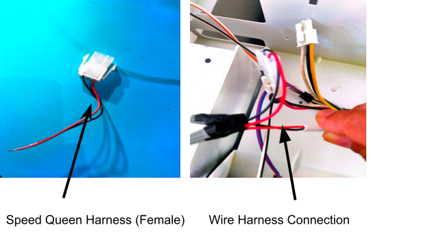
3) On the machine, you will see two identical male connectors — one yellow and one red.
👉 It is recommended to use the red male connector.
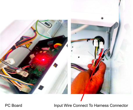
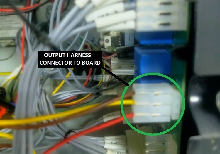
4) We provide a specific female harness connector to connect to the machine’s male connector.
5) Connect the Output Harness to the cable from the device, ensuring that the output negative (–) and positive (+) are correctly connected.
Coin Acceptor Installation
☞ For coin acceptor installation, it will capture token records as well as E-payment transactions.
1) For coin acceptor machines, use the yellow connector as shown in the picture below.
2) Connect the wire pulled from the back of the machine to the male and female connectors according to the INPUT and OUTPUT connections.
👉 For the Speed Queen machine, it is recommended to use 1.5 mm thick cables for the OUTPUT (-/+) connection.
3) Connect it to the machine’s male and female connectors, ensuring the INPUT and OUTPUT connections are correctly matched.
Device Installation - Speed Queen Stack Washer/Dryer & Single Washer
Cashless Device Installation
1) Place the device at the back of the machine or in a safe location where it will not be damaged.
2) Connect the wires to the output negative (–) and positive (+) , then loop them back to the input negative (–) and positive (+).
Quality Note - To Do Looping Input (-) to (+)
''Speed Queen Stack Dryer Connection''
1) For this machine model, the same harness connector will be used as other Speed Queen models. However, the wire connection from the Alpha-1/Device is slightly different.
👉 For the Speed Queen machine, it is recommended to use 1.5 mm thick cables for the OUTPUT (-/+) connection.
2) Open both the upper and lower coin acceptor casings.
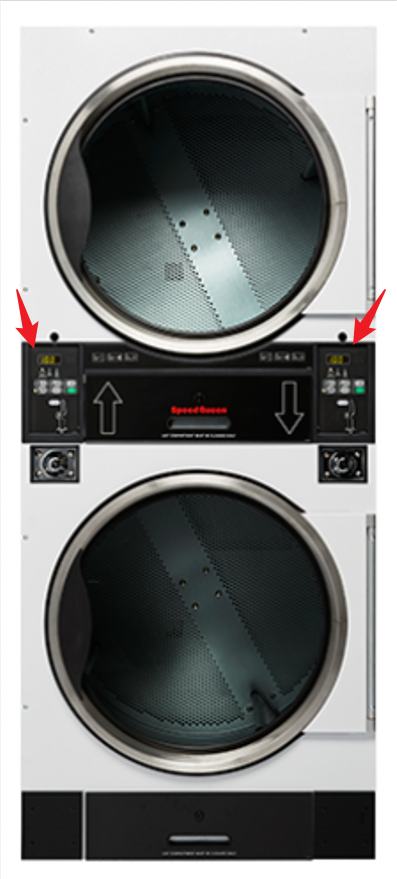
3) After opening the casing, you will see 4 screws at the end. Remove all 4 screws to access the inside of the machine.
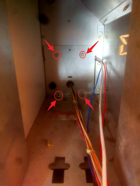
4) To pull the wire, start from the upper side of the casing.
5) The diagram below shows how the wire should be pulled in side the machine from the front to the back, where the device will be placed.
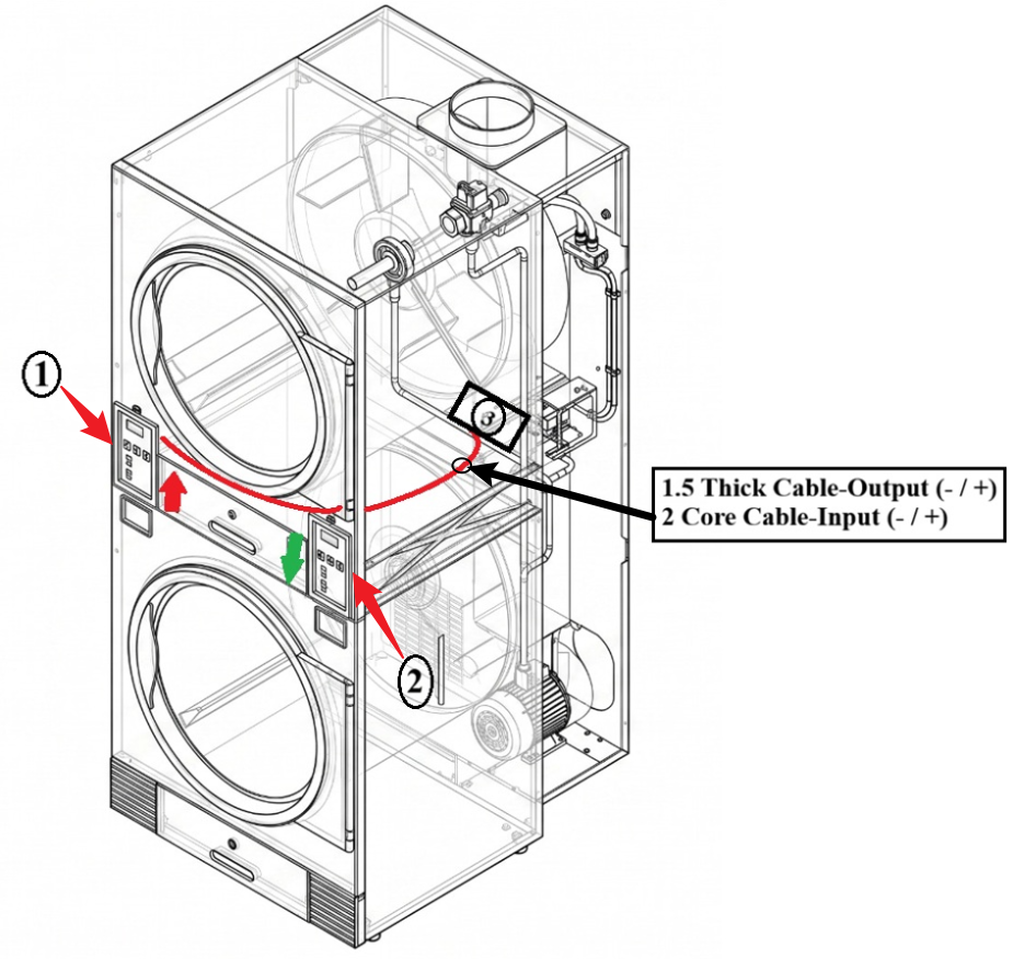
6) Cable Routing Steps for Left/UP (1) (Refer to Picture)
1. Route the cable from the top side (1) to the bottom side (2).
2. Pull the cable to the back of the machine.
3. Locate the small hole (3).
7) Cable Routing Steps for Right/Down (2) (Refer to Picture)
1. From the (2) bottom side, pull the wire straight to the (3) rear section.
There are other hoses passing near this hole, so pull carefully.
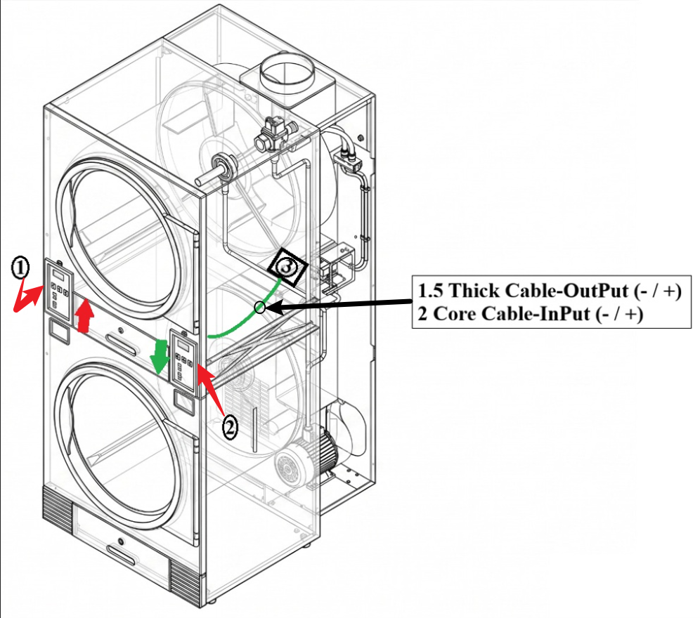
7) Feed/push the cable through the small hole (3) until you can see the cable coming out at the back of the machine.
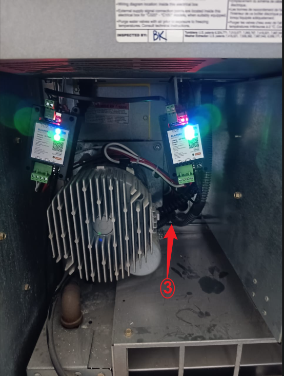
8) Pull the cable through hole (3) until it reaches the device installation location.
Click this link to next step:
IPSO - Installation
IPSO Washer/Dryer
Example: Dryer
Example: Washer
Harness Installation
- The IPSO machine has input and output connectors. Unplug them and connect them to the harness connector.

2. From the harness connector, connect the output and input to the 4-core wire from the device, following the input and output terminals. Ensure that the input and output negative (–) and positive (+) connections are correct.
3. For this machine, use a 1 mm or 1.5 mm thick cable for the output to ensure a better pulse signal.
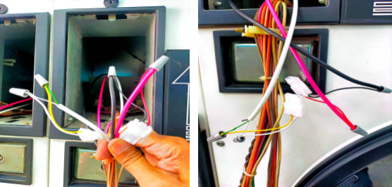
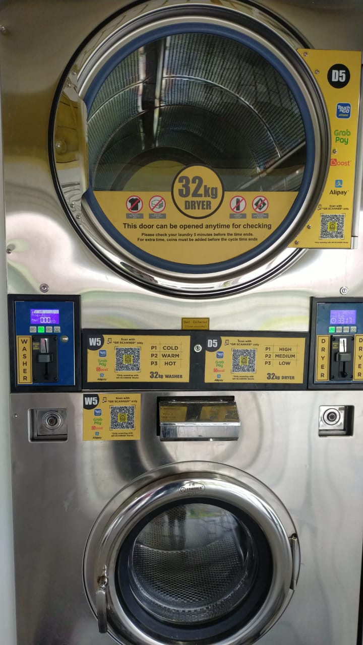
Go World - Installation
(A) From Chinese brands such as Go World, Octopus, and Oasis.
Example: Go World Stack Washer/Dryer
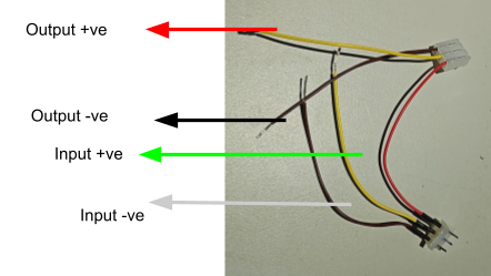
Washer/Dryer Harness connection
1. These models are equipped with a specific harness connector designed to connect to the machine’s board.
2. Connect the wire harness according to the input and output shown in the picture below from the Alpha-1 device .
(B) Go world dryer
3. As shown in the picture below, remove the connector from the board, connect the output to the board, and connect the input to the removed connector.
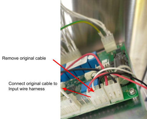
(C) Go World Washer
4. As shown in the picture below, remove the connector from the board, connect the output to the board, and connect the input to the removed connector.
5. Connect the input and output harness cables to the 4-core wire from the Alpha-1 device.
________________________________________________________________________________________________________________________________________________
(D) Looping in Alpha-1 for both Washer/Dryer
6. Loop the input negative( - ) and output negative( - ) to a common ground connection.
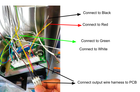
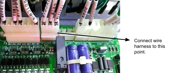
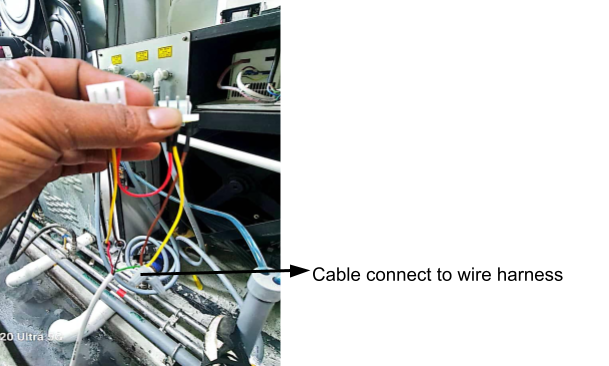
Fargo - Installation
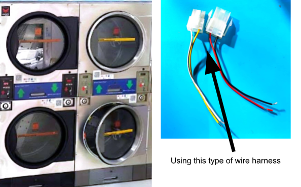
Example: Fargo Wire Harness
Fargo Harness connection Washer/Dryer
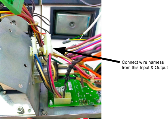
1. The Fargo machine comes with a specific connector. The coin acceptor cable from the machine also has a connector—remove it, then connect it to the provided wire harness, matching the male and female ends or the input and output connectors accordingly.
2. Connect the wire harness’s input and output lines to the 4-core wiring from the Alpha-1 device.
Example: Input & Output Connections
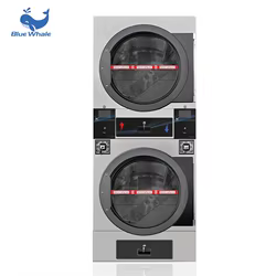
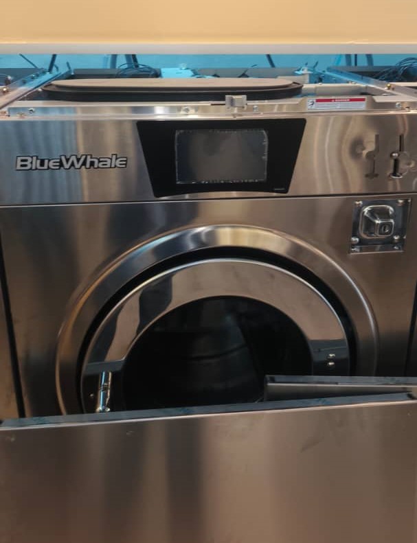
Blue Whale - Installation
Example: Blue Whale Stack Dryer & Washer
(A) Connection Washer/Dryer
1. Blue Whale machine, the connection is direct and simple. You will see three wires running from the board to the coin acceptor (Black, White, and Red).”
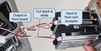
2. As shown in the picture above, cut the Black and White wires between the board and the coin acceptor. Then, connect the input and output using the 4-core wire from the device.
3. Leave Red wire
- Do not cut Red (it’s power). It should remain continuous from board.
4. Cut the Black & White wires
- Cut both Black and White roughly in the middle of their run.
5. Two sides after the cut
-
The ends coming from the board = OUTPUT (to the machine board).
-
Board-White → OUT+
-
Board-Black → OUT−
-
-
The ends going to the coin acceptor = INPUT (from the coin acceptor).
-
Acceptor-White → IN+
-
Acceptor-Black → IN−
-
6. Power ON and test
- Insert a coin/token, If the Coin Read in Node Cloud app shows pulses and the machine credit—done.
7. If it shows “No Pulse Detected”:
-
Confirm IN/OUT are not swapped.
-
Verify + and − on both input and output pairs.
-
Ensure the coin is actually accepted (a rejected coin won’t pulse).
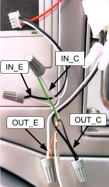
(B) Device Connection - ALPHA-1
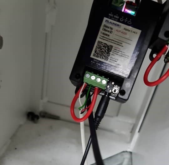
1. Devices will be placed behind the machine by screwing it using a specific screw.
2. Connecting the 4-Core Wire to the Device
-
Connect the 4-core wire to the device according to the terminal markings:
-
Input (IN−, IN+)
-
Output (OUT−, OUT+)
-
-
After wiring, make a loop connection between:
-
IN− (Input negative)
-
OUT− (Output negative)
-
-
Ensure all connections are secured and insulated before powering ON.
________________________________________________________________________________________________________________________________________________
Blue Whale Cashless Machine (Non-Coin Acceptor)
(A) Wire connection Dryer
 Dryer Connector
1. Locate the cashless connector
-
Identify the two output wires shown in your picture:
-
White = Output (−)
-
Green = Output (+)
-
2. Dryer cashless machines with a connector as shown in the picture above, use the output connection only. Tap into the two wires: White (Output Negative −) and Green (Output Positive +), using a 2-core cable from the device.
(B) Wire Connection Washer
 Washer connector
1. Locate the cashless connector
-
Identify the two output wires shown in your picture:
-
Pink = Output (−)
-
Red = Output (+)
-
2. Washer cashless machines with a connector as shown in the picture above, use the output connection only. Tap into the two wires: Pink (Output Negative −) and Red (Output Positive +), using a 2-core cable from the device.
(B) Device Connection - ALPHA-1
![]() Quality Note: Looping From Input (-) To (+)
Quality Note: Looping From Input (-) To (+)
1. Devices will be placed behind the machine by screwing it using a specific screw.
2. Connecting the 2-Core Wire to the Device.
-
Connect the 2-core wire to the device according to the markings:
-
Output (OUT−, OUT+)
-
-
After wiring, make a loop connection between:
-
INPUT− (Input negative)
-
INPUT− (Input positive)
-
-
Ensure all connections are secured and insulated before powering ON.
________________________________________________________________________________________________________________________________________________
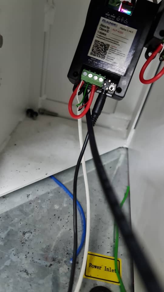
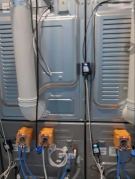
Power Supply Connection for Blue Whale Machine
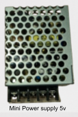
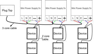
![]() Quality Note: 5v Power Supply Required
Quality Note: 5v Power Supply Required
1. For the Blue Whale machine, each device must have its own dedicated power supply. For example, one device requires one power supply. If there are five devices, you must use five separate power supply connections, as shown in the image above.
________________________________________________________________________________________________________________________________________________
Blue Whale New Version
1) The new version will use a specific harness cable, and the deice power can take from machine .
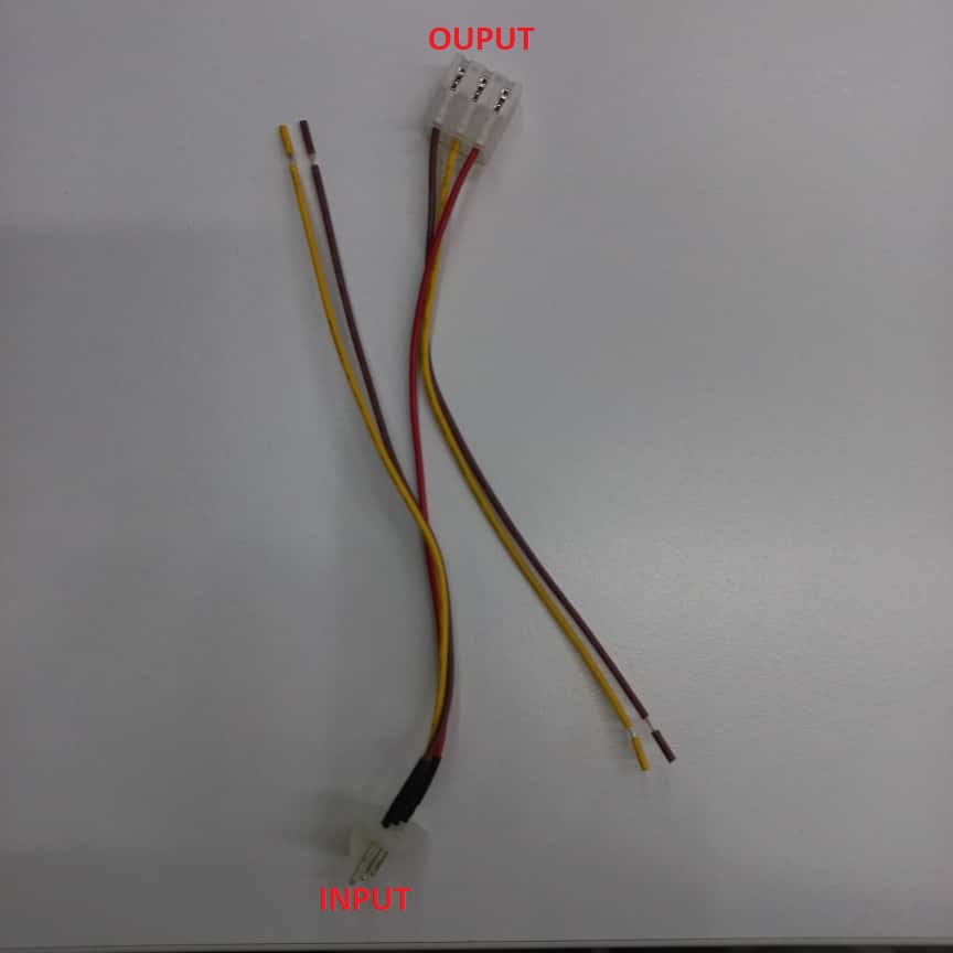 HARNESS CABLE
2) Before we start install device, prepare both a 4-core and a 2-core cable for connecting the device.
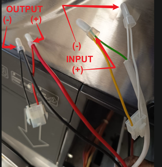
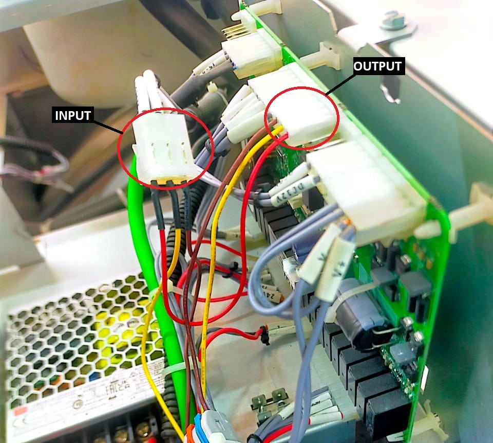
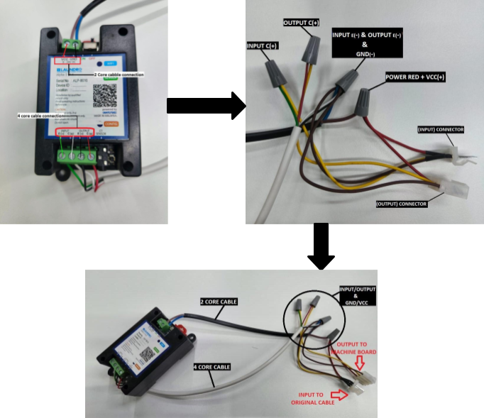 INPUT/OUTPUT & GND-/VCC+
3) Step by step connection return below.
- Use a 4-core cable to connect the device’s INPUT E(-)/C(+) and OUTPUT E(-)/C(+) points.
- From the device, take INPUT E(-), OUTPUT E(-), and GND (-), join them together, and connect to the 'harness cable' INPUT and OUTPUT connections (CHOCLATE ).
- From the device, take the INPUT C(+) and connect it to the 'harness cable' INPUT (YELLOW ).
- From the device, take the OUTPUT C(+) and connect it to the 'harness cable' OUTPUT(YELLOW ).
- From the device, take the VCC (+) and connect it to the red wire on 'the harness cable' (RED )
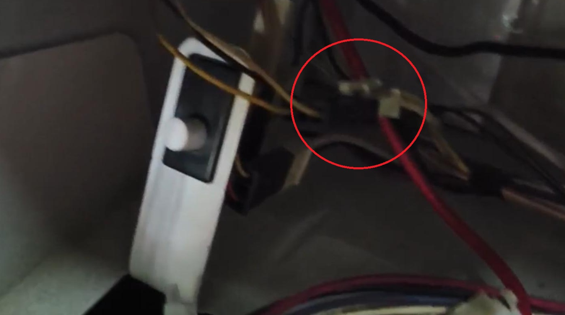
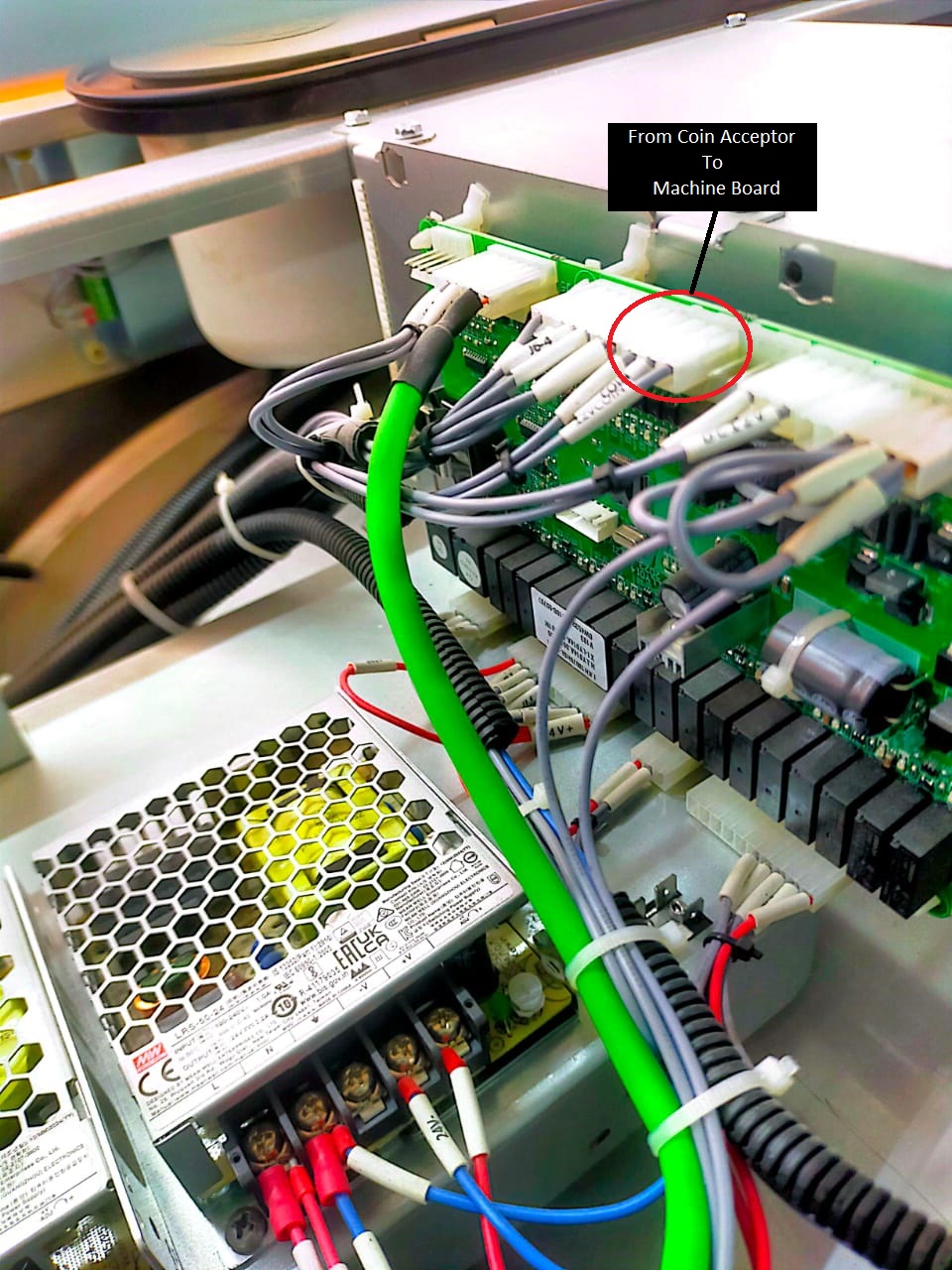
4) Follow the step-by-step connection procedure and connect it to the machine board.
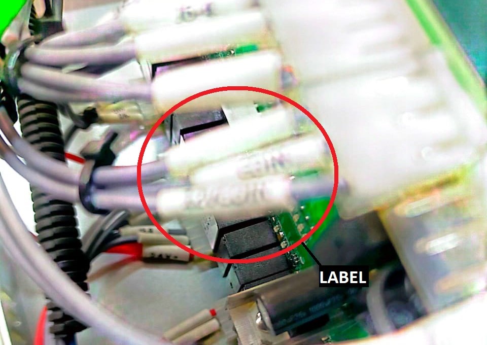
- If you are not sure which connector to use, refer to the red-circled label on the cable in the picture. The coin acceptor cable has the same label, so you can match the labels to identify the correct connector on the board.
- Find the correct connector by pulling out the cable. Connect it to the harness cable INPUT, then connect the harness cable OUTPUT to the board.
WASHER
1) The new version will use a specific harness cable, and the deice power can take from machine .
2) Before we start install device, prepare both a 4-core and a 2-core cable for connecting the device.
 Device To Harness Cable Connection
3) Step by step connection return below.
- Connect the device INPUT E(-) (White wire) to the harness cable INPUT (Brown wire).
- Connect the device INPUT C(+) (Green wire) to the harness cable INPUT (Yellow wire).
- Connect the device OUPUT E(-) (Black wire) to the harness cable OUTPUT (Brown wire).
- Connect the device OUTPUT C(+) (Red wire) to the harness cable OUTPUT (Yellow wire).
4) Follow the step-by-step connection procedure and connect it to the machine board.
WASHER BOARD ORIGINAL CONECCTION
 WASHER BOARD HARNESS CABLE CONNECTION
5) Find the correct connector by pulling out the cable. Connect it to the harness cable INPUT, then connect the harness cable OUTPUT to the board.
6) The device will receive power from the machine’s existing power supply. Since there are two power supplies present, use the one that provides 12V.
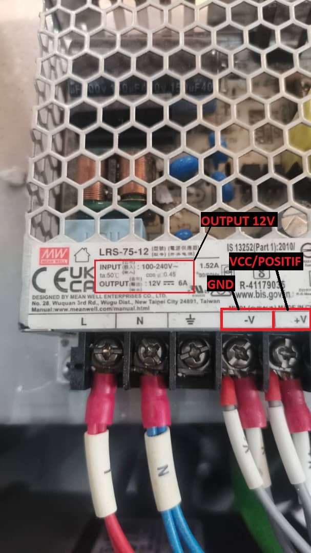 Machine Power Supply
7) After completing all the connections, power on the machine. The device’s blue indicator light will begin blinking.
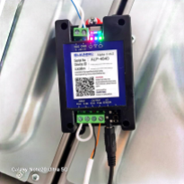
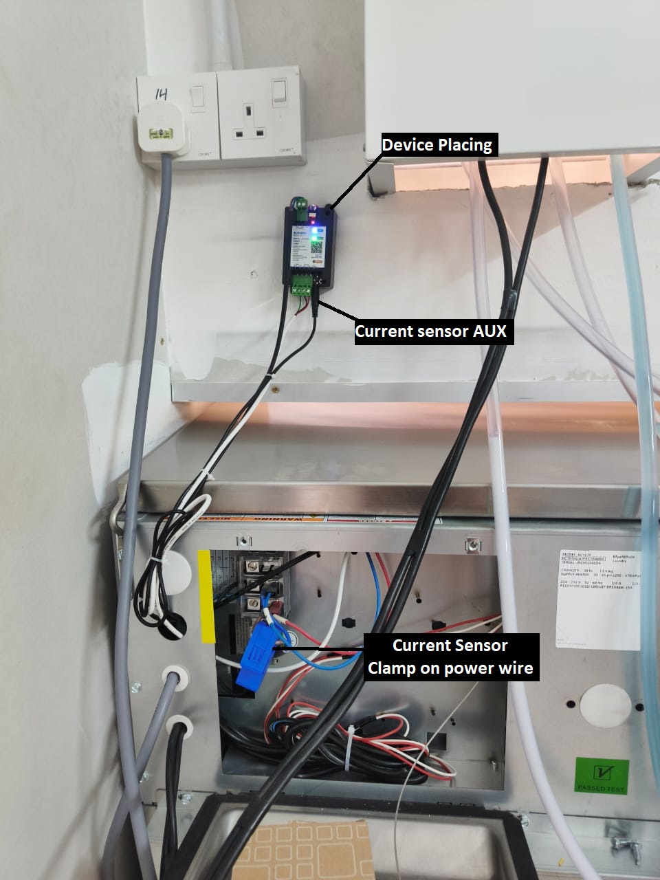 CURRENT SENSOR & DEVICE PLACING
8) You may place the device in the position shown in the picture, or any safer location where it will not be damaged.
9) Clamp the current sensor onto the machine’s positive power wire, and connect the AUX plug to the device.
WIFI Configuration (ALPHA-1)
(A) Step-By-Step WIFI Configuration
1. Login to Node-Laundro application (https://node.thelaundro.com/login) using given username and password.
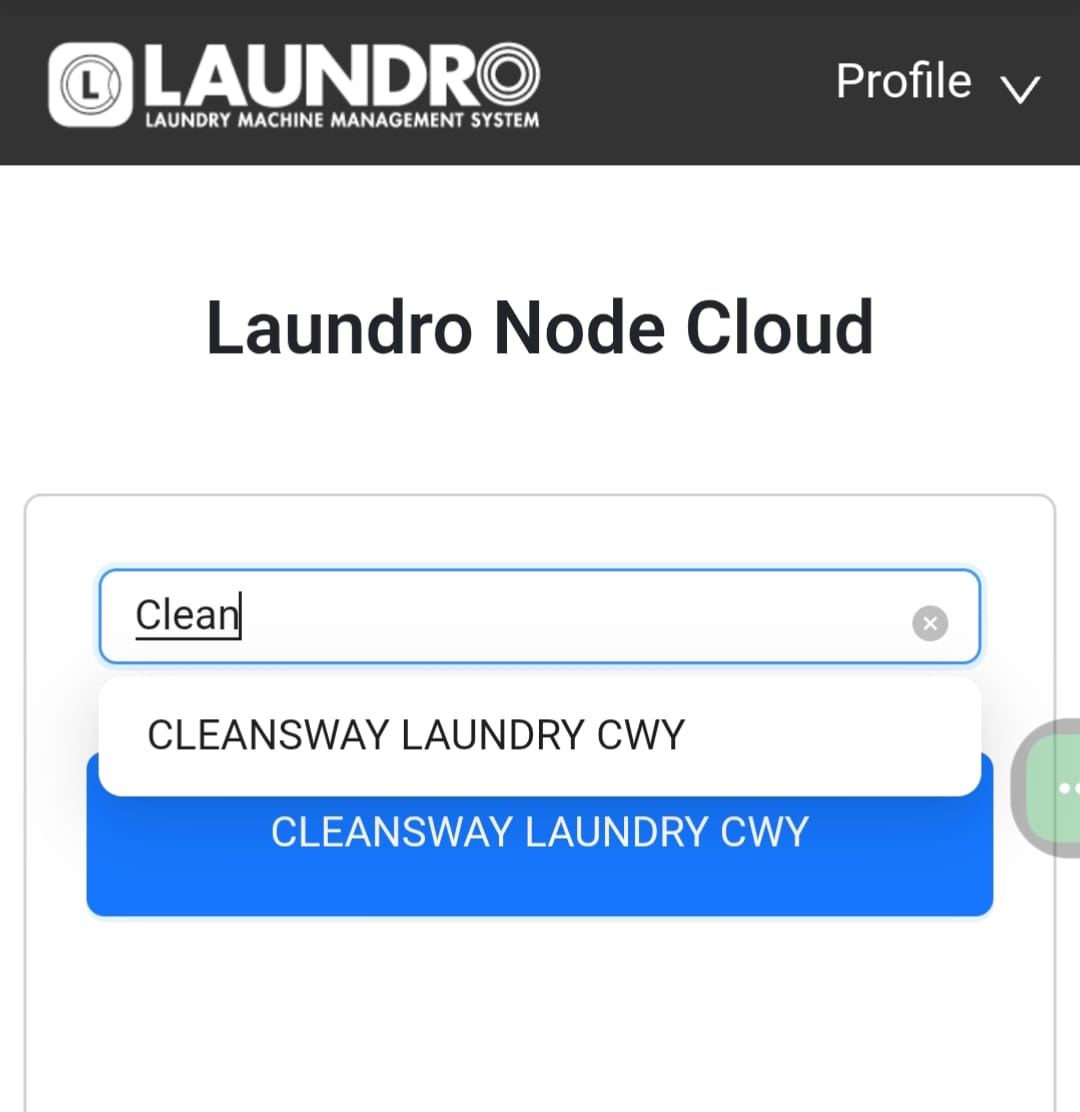
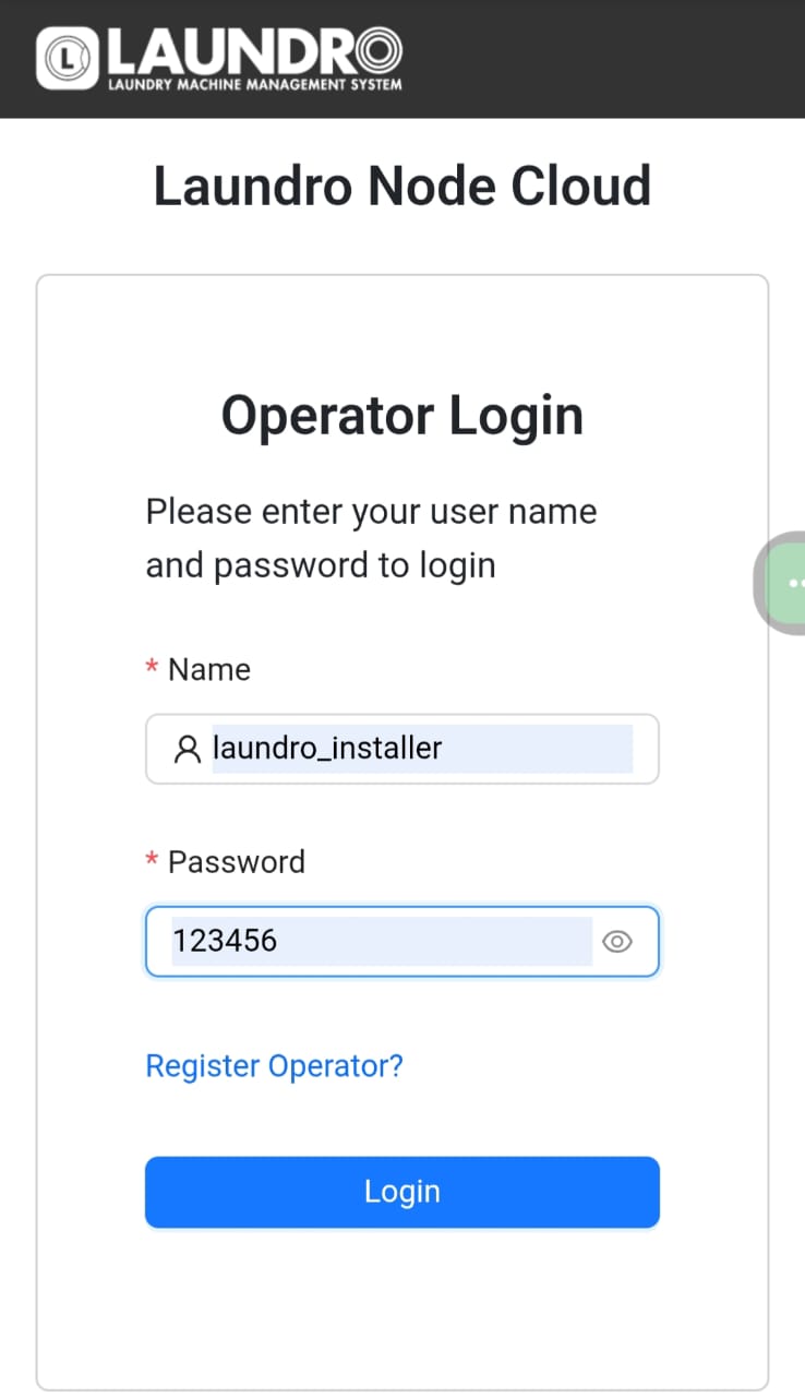 Example: Login Page
2. Search using the outlet name or ID provided, then click on the outlet to view its details.
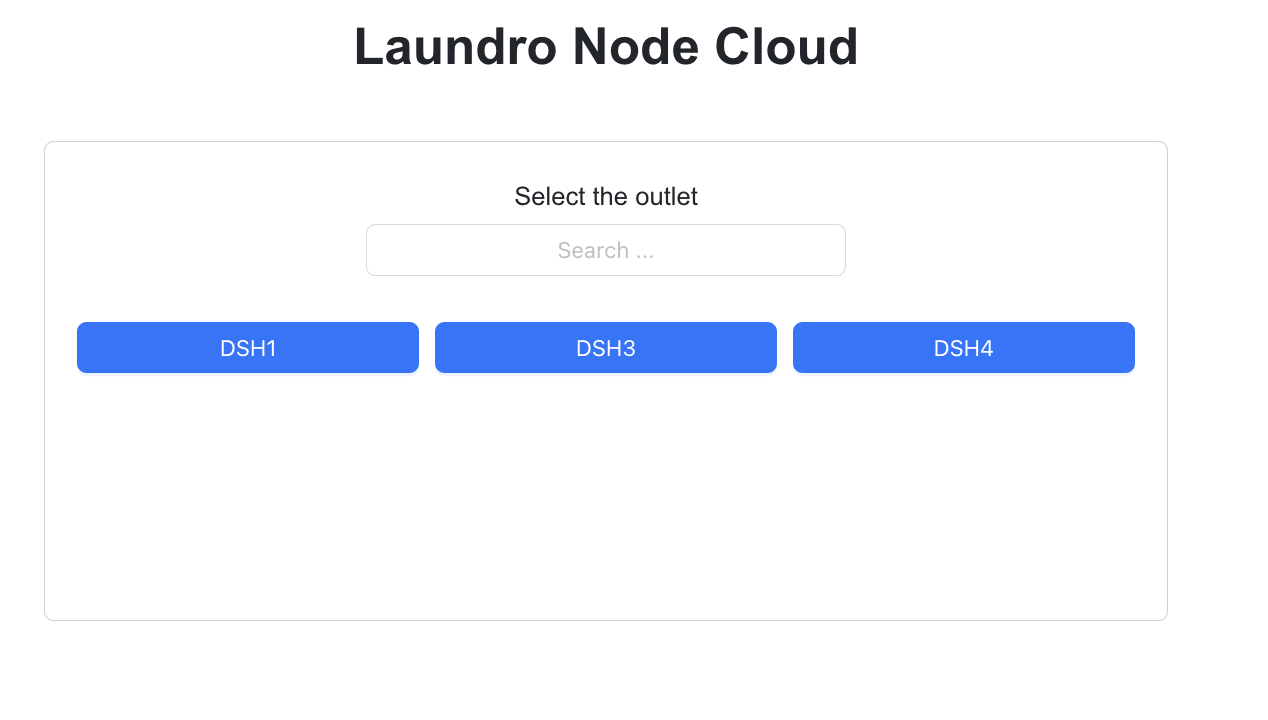
3. By selecting an outlet name, you will be directed to the outlet details page. On this page, verify that all machine counts and details are correct before proceeding to the next step.
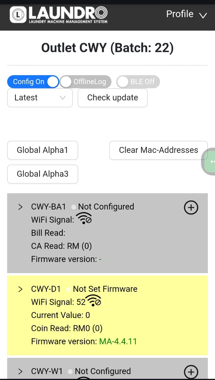
4. Click on enable config mode to allow this outlet to be configurable.
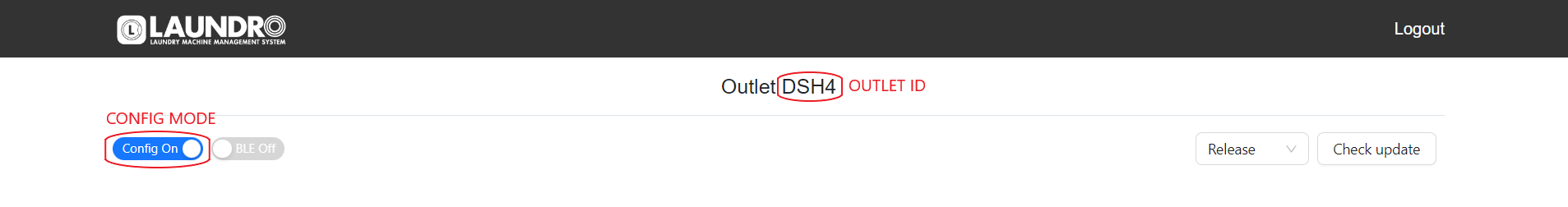 Example: On Config Mode
5. All machine details will be displayed in grey, indicating they are ready to be configured. Once a device is successfully configured, the background colour will change.
 Example: Before configure device in grey colour
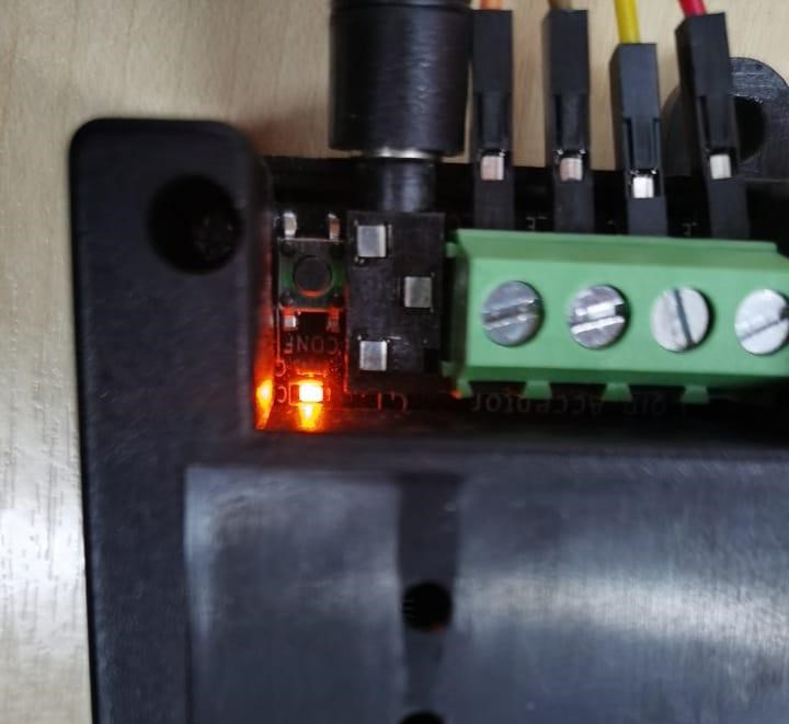
6. Turn on the switch on the Alpha-1 device and wait for the blue light to start blinking. This indicates that the device is ready for configuration.
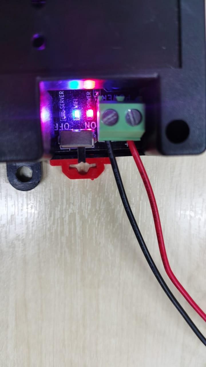 Example: Blinking blue light show it’s waiting for connection
7. Using your mobile phone, open the Wi-Fi settings. You will see the Laundro ID appear, as shown in the picture below.
8. Connect to newly broadcasted WiFi using default password (123456789)
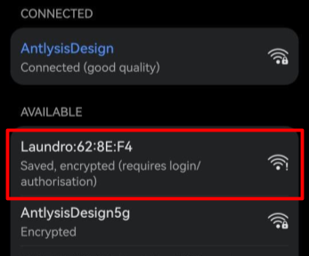 Example: Alpha-1 Laundro I'D
9. Once connected to the Laundro Wi-Fi, a pop-up will appear directing you to the Wi-Fi Manager page.
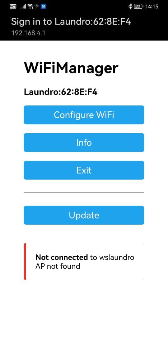 Example: WIFI Manger Page
💡 Tip:
- If the page doesn’t pop up, simply type 192.168.4.1 into your browser’s address bar, and the Wi-Fi Manager will open.
- Only for ''SAMSUNG'' Mobile follow the steps below.
-
Connect your Samsung mobile to the Laundro Wi-Fi.
-
An Internet Connection pop-up will appear. Tap “Always Connect.”
-
Tap the ⚙️settings icon.
-
Select “Manage Router.”
-
The Wi-Fi Manager page will open.
10. Press ‘Configure WIFI’ to open the configuration page. Then, select the correct SSID, enter the password, and the Outlet ID following in Node Cloud.
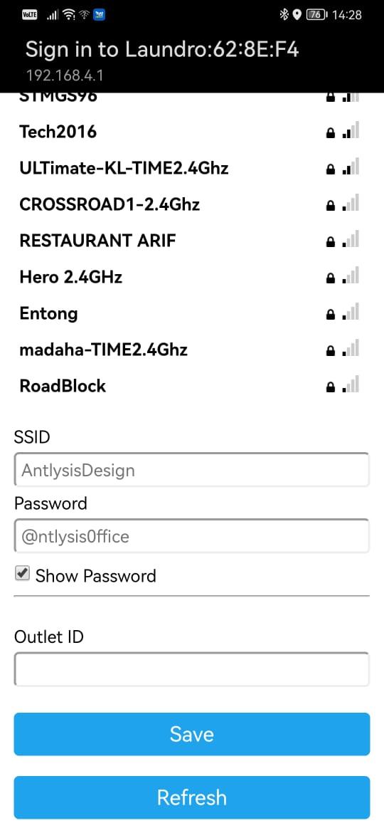 Example: WIFI Selection Mode
⚠️ Warning: Ensure that the Outlet ID and Wi-Fi password are correct. Also, check that there are no spaces before or after the characters before saving.
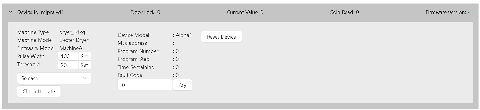
11. Once the device is successfully configured to Wi-Fi, the orange and green lights will appear. You can now proceed to the cloud setup.
⚠️ Warning: Ensure all devices have their WIFI configured before proceeding to the next step.
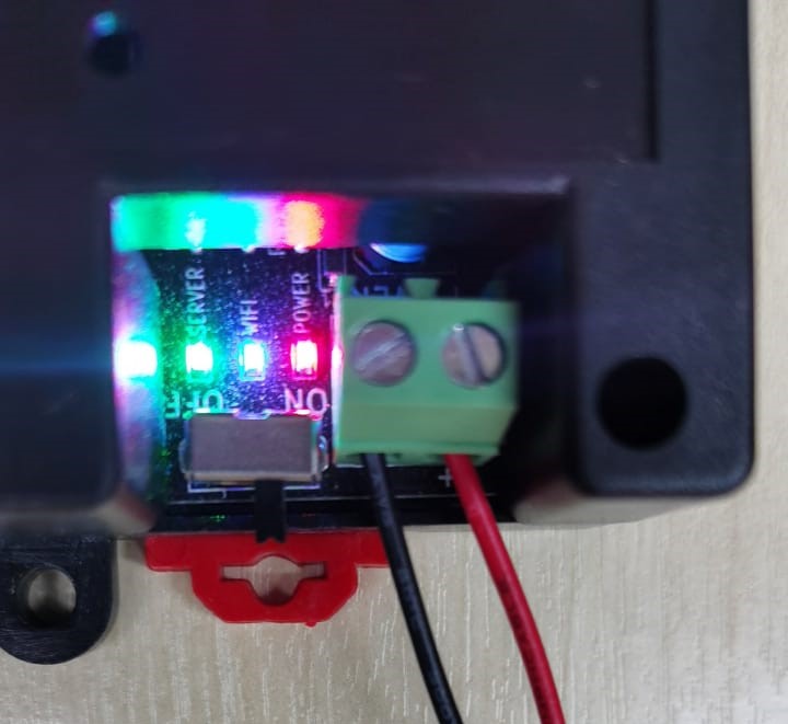
Example: Configuration LED and other 3 LEDs (Power, WIFI & Server) are lighted up
________________________________________________________________________________________________________________________________________________
(B) Steps of Cloud Configuration
1. Log back in to the Node-Laundro application https://node.thelaundro.com/login using the provided username and password. Then, follow the steps in ''(A) Step-by-Step WiFi Configuration'' until you reach the ''Outlet Detail Page.”
2. Stay on this page. You will need to press the (+) icon later, but first, continue following the next steps.
3. On the device, you’ll see a configure button next to the orange light. Press it, and the orange light will begin blinking.
Example: Config Button near Orange LED (Config)
4. Once the orange light starts blinking, you can press the plus (+) icon, and the Mac address will pop up.
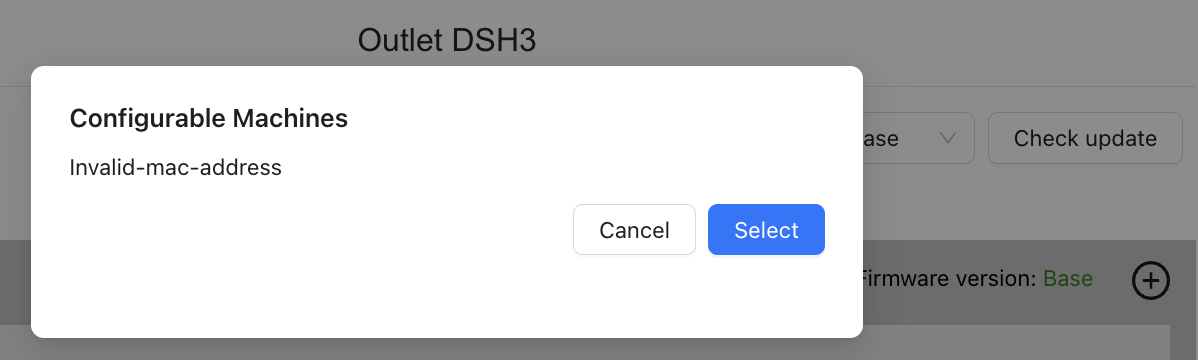
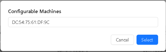
5. Once the MAC address pops up, click Select.
6. After selecting the correct MAC address, the section you configured from grey will turn yellow.
 Example: Section from Grey turn to Yellow
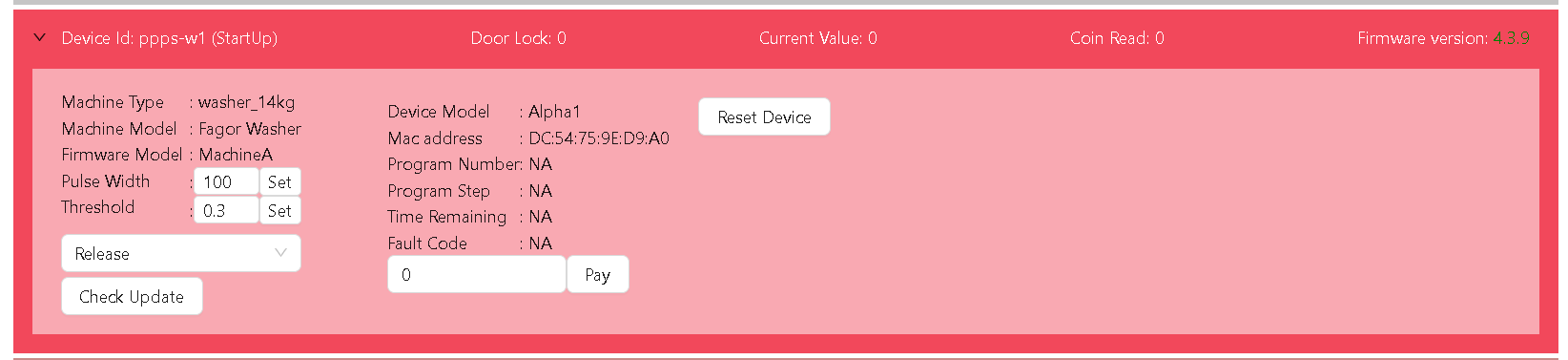
7. Select the latest option, then click Check Update. The latest version will appear, and you can click Update
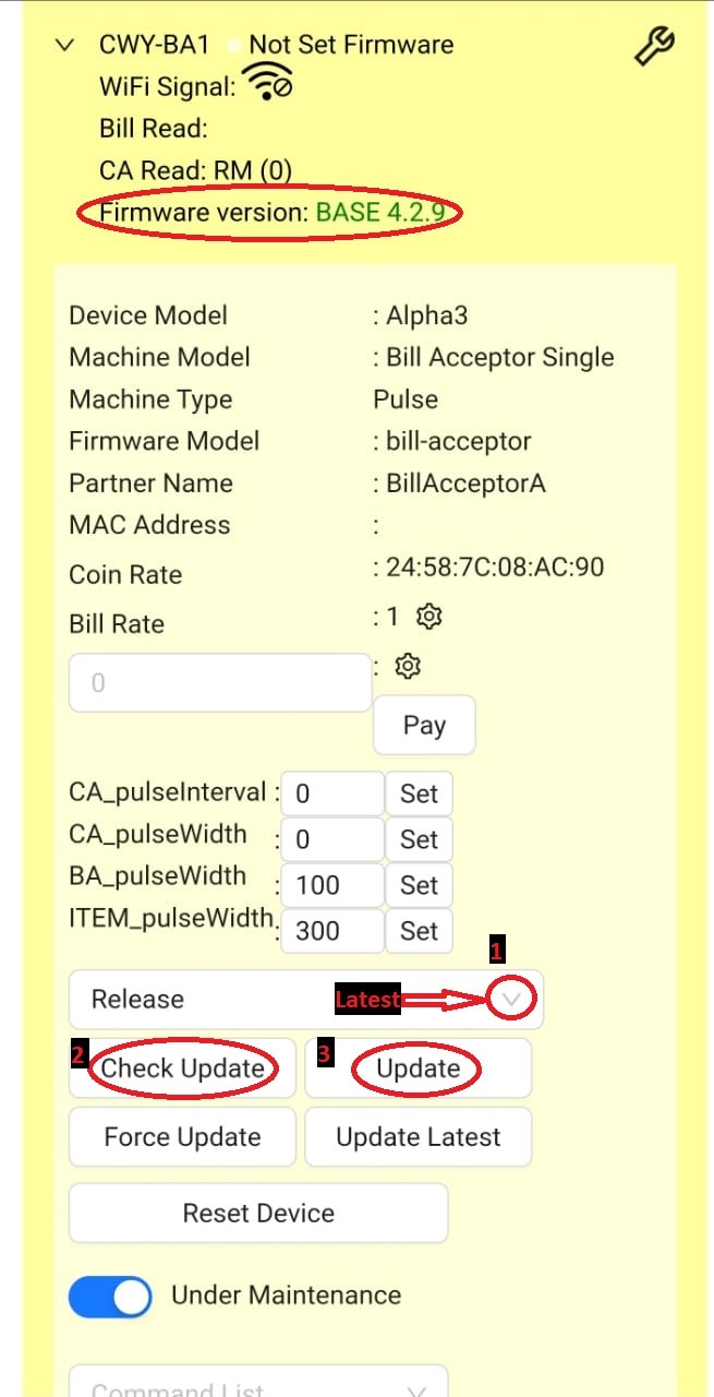 Example: Step by step check update
![]() Quality Note: If configuration is done in the wrong section:
Quality Note: If configuration is done in the wrong section:
-
-
In the Cloud App, click Reset Device.
-
On the device, long press the Configure button until the orange light appears.
-
Select the correct machine ID and repeat the step with the Plus (+) Icon.
-
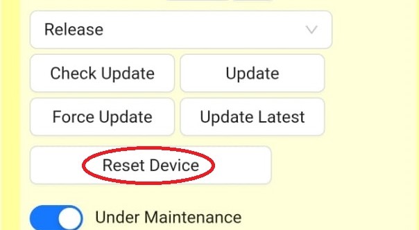 Example: Reset Device on app
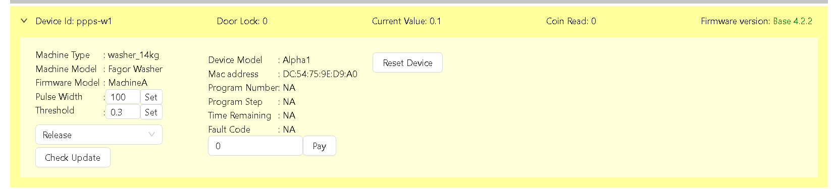
8. Once the update is successful, the section will turn blue colour. You can then proceed with testing.
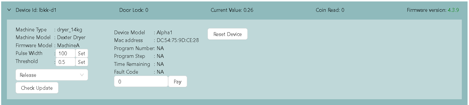 Example: Blue Colour Ready For Testing
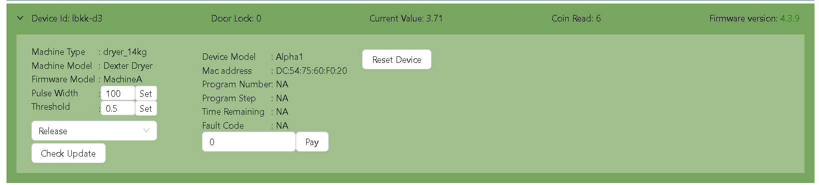
9. When the machine’s ‘Current Value’ exceeds the ‘Threshold’ value, the machine status will turn green.
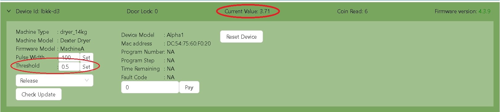 Example: Current Value increase Threshold Value
(C) Status on Node
Machines are displayed with 6 types of status.
-
Grey - Not configured
-
Yellow - Pending Update
-
Blue - Idle status
-
Green - Running Status
-
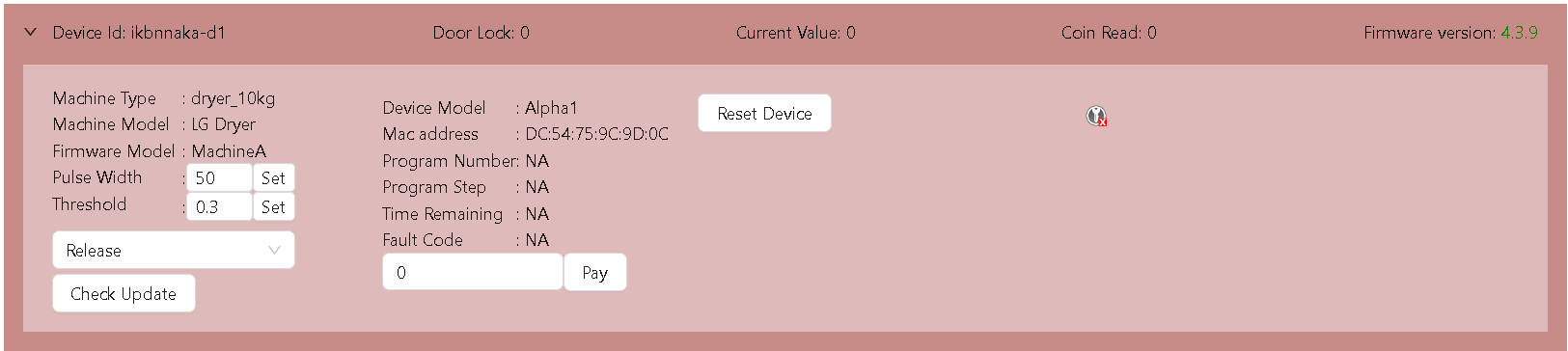
Red - Offline Status
-
Bright red - Abnormal Status
Electrolux - Installation
Alpha1 v4 to v5 Firmware Migration Procedure
This document provides the technical steps required to migrate device partitions and upgrade to the latest production firmware.
1. Initial Firmware Preparation
2. Pre-Migration Validation
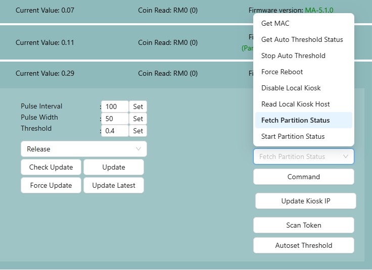
Execute the Fetch Partition Status command from the conmmand list to determine the migration state.
| Response | Action |
|---|---|
PartitionMigration_Uninitiated |
Proceed to Migration |
PartitionMigration_NotStarted |
Proceed to Migration |
PartitionMigration_Completed |
Migration not needed; skip to Phase 4 |
PartitionMigration_ErrorReadingStatus |
Stop and report issue |
PartitionMigration_Failed |
Stop and report issue |
3. Partition Migration Process
- Select Start Partition Migration from the command list and click Command.
- Observation: The device may reboot twice. Do not interrupt power during this time. The entire process may take around 2-5 minutes.
- Success Criteria: The migration is successful when
PartitionReformat_Successis published and the device reboots. - If
PartitionReformat_Successdoes not appear before device reboot, select Fetch Partition Status after the device reboots and click Command. IfPartitionMigration_Completedis published, proceed with device update, IfPartition_MigrationInProgressis shown, wait for next reboot before updating.
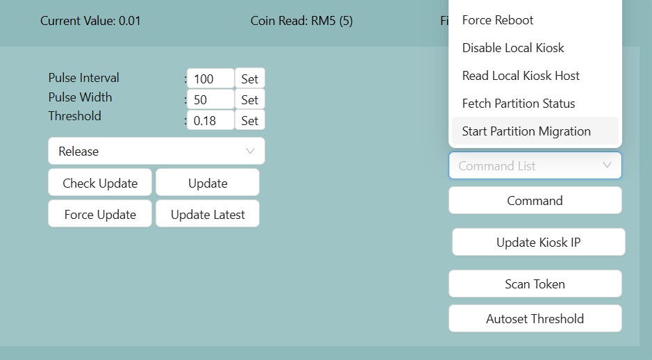
[!CAUTION] If PartitionReformat_Fail or PartitionReformat_CriticalFail is displayed, do not proceed. Report the failure immediately!
4. Final Firmware Update
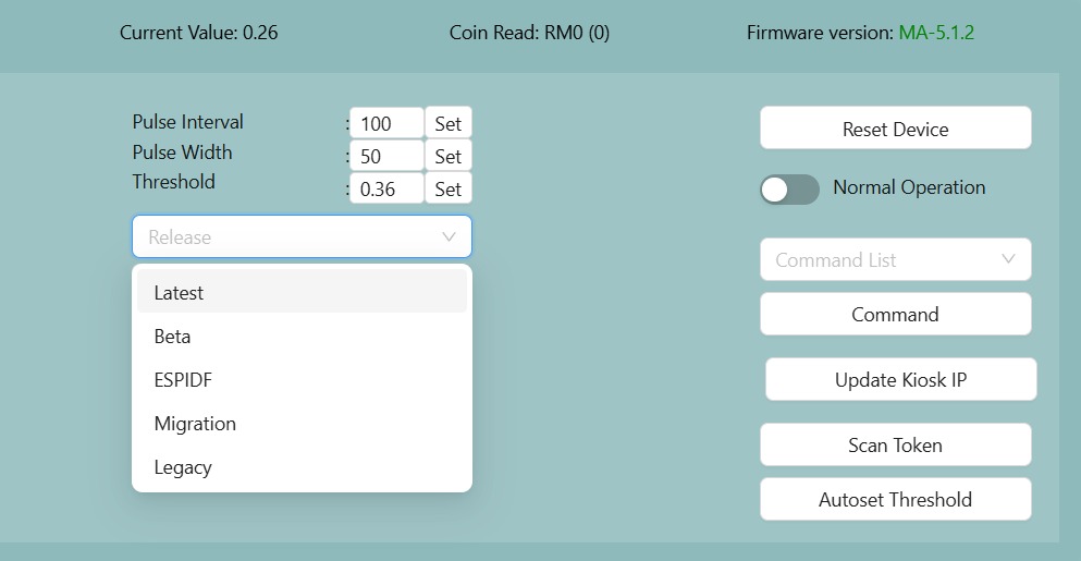
- Select Latest in the Release dropdown menu.
- Click Check Update.
- When prompted with "5.X.X available", click Update.
- Verification: Following the reboot, ensure the firmware version is updated to XX-5.X.X.
If still intent to use legacy, use the legacy release (firmware version will be 4.4.11)
Procedure to Flash Alpha device
Prerequisites
Before starting, ensure you have the following:
- Download Flashing tool and latest firmware here -> Flashing Tool.zip
- Windows laptop/pc (recommended)
- microUSB cable
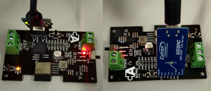
- Cytron USB-UART Converter UC00C (shown below)
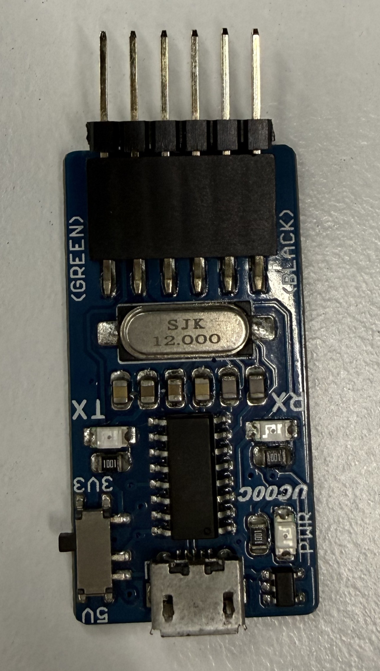
Flashing Procedure
- The programmer pins must be exposed via male headers at a 2.54mm pitch
-
Pin Order: Ensure the pins are arranged in this specific sequence:
-
DTR
-
RX
-
TX
-
3.3V
-
RTS
-
GND
-
- Insert the programmer into the flashing female port of the board, matching the pin names except for TX and RX, which are typically swapped.
- Tilt the programmer at an angle to ensure a solid electrical connection with the port.

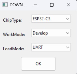
- Open the downloaded Espressif Flash Download Tool (Flashing Tool -> flash_download_tool_3.9.4).
- Upon opening the software, select the following settings:
- Chip Type: ESP32-C3
- WorkMode: Develop (for single board) or Factory (for multiple boards)
- LoadMode: UART

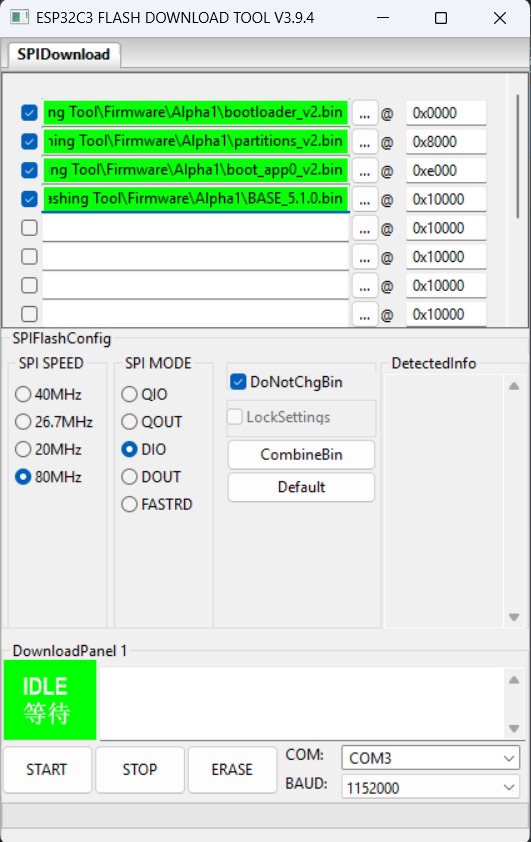
- Set the file paths at the following addresses:
File Name Memory Address (Offset) bootloader_v2.bin0x0000 partitions_v2.bin0x8000 boot_app0_v2.bin0xe000 AlphaX_BASE_x.x.x.bin0x10000 The files can be located at: Flashing Tool -> Firmware -> (select device model eg: Alpha1)
PLEASE USE THE LATEST FILES PROVIDED IN THE ATTACHED FILE ABOVE
- Configure the SPI Flash Config section as follows:
- SPI SPEED: 80MHz
- SPI MODE: DIO
- Baud Rate: 921600
- The flashing process:
- For Single Boards:
- Select the appropriate COM port
- Click "START" to begin.
- Monitor the progress bar as the upload proceeds.
- For Multiple Boards (Factory Mode)
- Uncheck "LockSettings" to modify configurations.
- Assign the correct COM port for each attached programmer.
- Re-check "LockSettings" to secure the configuration.
- Click "START ALL" to flash all boards simultaneously.
NOTE: It is recommended to ERASE the board first before re-flashing it. This can be done by pressing ERASE in the flashing tool before flashing.

- For Single Boards:
Verification
Once the upload is complete, look for the following indicator on the board:
- The blue, green, and yellow LEDs will flash twice to signify a successful firmware upload
- The blue led will start blinking continuously indicating that device is ready to be setup and configured
Alpha1 Latest Firmware Overview
Latest Version: 5.1.4
Platform: ESP32-C3
Framework: ESP-IDF
Overview
Alpha1 v5 is an IoT firmware solution designed primarily for the intelligent management of commercial washers and dryers in laundromats, alongside general vending and payment system integration. Built on the ESP32 platform using the ESP-IDF framework, this firmware provides comprehensive connectivity, monitoring, and control capabilities tailored for various laundromat machine types and stacked configurations.
Features
- Multi-Environment Support: Configurable for different machine types (BASE, MachineA, MachineB, MachineC, StackA, KioskCAA, GasSensorA)
- Real-time Monitoring: Current sensing, pulse detection, and status reporting
- Secure Connectivity: WiFi management with captive portal and MQTT communication
- Payment Processing: Support for coin and electronic payment systems
- Remote Management: OTA updates, configuration management, and remote diagnostics
- Data Persistence: Critical data backup and recovery with NVS storage and LittleFS file system
- Web Interface: Built-in web server with responsive UI (embedded HTML/JS/CSS) for device configuration
- Auto-calibration: Intelligent threshold calibration for optimal performance
Architecture
Core Components
Main Application (src/main.c)
The main application orchestrates all system components and provides:
- Environment-specific machine type selection
- Global variable management
- System initialization and task coordination
- Event handling and queue management
Configuration Management (src/Alpha1_configurations.h)
Centralized configuration system defining:
- Device configuration structures
- Machine type definitions
- Queue message enumerations
- Auto-threshold calibration parameters
Machine Types
1. BASE Environment
- Purpose: Factory default firmware flashed onto every new device before deployment
- Features: WiFi connectivity, OTA update capability, and cloud communication. No machine-specific logic. Once the device is registered in the Node Cloud platform, the operator selects the machine type and the correct firmware is pushed to the device over-the-air.
- Build Flag:
-D BASE
2. MachineA / MachineB / MachineC Environments (src/Machines/MachineX.h/.c)
-
Build Flags:
-D MACHINE_A,-D MACHINE_B,-D MACHINE_C -
MachineA — Standard coin-op washer or dryer. Uses CT current sensing to detect running/idle cycles and a timer-based pulse reader to count coin drops. Lock data records both the start and end of each cycle. Supports local kiosk MQTT and auto-threshold calibration.
-
MachineB — Detergent dispensers, water vending machines, and similar coin/bill-operated product dispensing equipment. No current sensing or cycle tracking. Counts bill/token pulses using a timer-based reader. Transaction completion is determined by an inactivity timeout (lock-check counter) rather than a CT sensor transition.
-
MachineC — Commercial washer or dryer using a hardware rising-edge GPIO interrupt for coin pulse detection instead of a timer. CT current sensing and lock data work the same as MachineA. Includes a noise filter on the pulse reader during active cycles and supports local kiosk MQTT.
3. StackA Environment (src/Machines/StackA.h/.c)
- Purpose: Advanced stacked machine system (shared motherboard)
- Features:
- Multiple payment methods (coin, epay, cash advance)
- Enhanced current monitoring
- Extended payment processing capabilities
- Advanced status reporting
- Build Flag:
-D STACK_A
4. KioskCAA Environment (src/Machines/KioskCAA.h/.c)
- Purpose: Centralized kiosk management integration
- Features: Kiosk-based payment routing and control
- Build Flag:
-D KIOSKCA_A
5. GasSensorA Environment (src/Sensors/GasSensorA.h/.c)
- Purpose: Dryer cycle monitoring via gas tong pulse detection
- Features: Connects to the gas tong (burner assembly) signal line of gas-powered dryers. Counts pulses each time the burner fires to track dryer cycle runs. Tracks both a current pulse count and a lifetime cumulative total, reported periodically to the cloud. No payment processing, no current sensing.
- Build Flag:
-D GASSENSOR_A
Managed Components
Common Core Component
Connectivity Components
wifi_app: WiFi connection management and captive portalmqtt_app: MQTT client for cloud communicationwm_app: WiFi Manager for network configurationsntp_app: Network time synchronization
Data Management Components
nvs_app: Non-volatile storage managementcriticalData_app: Critical data backup and recoveryota_app: Over-the-air firmware updates
Hardware Interface Components
pulse_app: Pulse detection and countingct_app: Current transformer interfaceui_app: User interface and LED management
File Structure
src/
├── main.c # Main application entry point
├── Alpha1_configurations.h # Global configuration definitions
├── Machines/
│ ├── MachineA.h/.c # MachineA implementation
│ └── StackA.h/.c # StackA implementation
├── Sensors/
│ └── GasSensorA.h/.c # Gas sensor interface
└── webpage/
├── index.html # Web interface HTML
├── code.js # Client-side JavaScript
└── style.css # Styling
Build Environments
Prerequisites
- PlatformIO
- ESP-IDF framework
- ESP32-C3 development board
Environment Configuration
BASE Environment
pio run -e BASE
- Minimal feature set
- Basic monitoring capabilities
Machine Environments (MachineA, MachineB, MachineC)
pio run -e MachineA
# or MachineB, MachineC
- MachineA/C: CT current sensing, coin pulse detection, cycle-based lock data
- MachineB: Bill/token pulse counting for detergent vending, water vending, and similar dispensing machines, inactivity-based transaction completion
StackA Environment
pio run -e StackA
- Dual-payment system
- Support for coin, epay, and cash advance
Specialized Environments
pio run -e KioskCAA
pio run -e GasSensorA
- KioskCAA: Central payment routing to machines on the floor
- GasSensorA: Dryer cycle counting via gas tong pulse detection
Build Configuration
The firmware uses environment-specific build flags defined in platformio.ini:
[env:BASE]
build_flags = ... -D BASE
[env:MachineA]
build_flags = ... -D MACHINE_A
[env:StackA]
build_flags = ... -D STACK_A
Custom Firmware Extraction
A custom Python script (copyFirmware.py) is embedded in the build process via extra_scripts. It copies the resulting binaries into release folders automatically.
Partition Setup
The project defines custom board partitions using alphaX_partitions.csv, efficiently structuring the ESP32-C3 flash for Application, NVS, LittleFS, and OTA logic.
Hardware Requirements
- MCU: ESP32-C3 DevKit M-1
- Flash: Minimum 4MB
- RAM: 400KB SRAM
- Connectivity: WiFi 802.11 b/g/n
- ADC: For current sensing
- GPIO: For pulse detection and LED indicators
Pin Configuration
- Current sensing via ADC
- Pulse input detection
- Status LEDs (WiFi, MQTT, Config)
- Configuration and reset buttons
Installation
-
Clone the repository:
git clone https://github.com/Antlysis/Alpha1-v5.git cd Alpha1-v5 -
Install dependencies:
pio pkg install -
Build for specific environment:
# For MachineA pio run -e MachineA # For StackA pio run -e StackA # For BASE pio run -e BASE -
Upload firmware:
pio run -e MachineA -t upload
Configuration
Initial Setup
- Power on the device
- Connect to the WiFi access point
Laundro:XX:XX:XX - Navigate to
192.168.4.1in a web browser if configuration portal does not open automatically - Configure WiFi credentials and outlet parameters
MQTT Configuration
- Broker: Configurable via web interface
- Topics: Auto-generated based on device MAC address
- QoS: Configurable per message type
- Last Will: Automatic disconnect detection
Device Parameters
- Outlet ID: Unique identifier for the machine
- Device IDs: Primary and secondary device identifiers
- Pulse Configuration: Width and interval settings
- Threshold Values: Current detection thresholds
API Reference
Machine Interface Functions
MachineA/StackA Common Functions
void machine_begin(Alpha1_t *conf); // Initialize machine
void machine_status(char *status, criticalData_t *lockData, char *time); // Get status
int machine_pay(char* payload); // Process payment
bool machine_command(char *payload, int length, char *response); // Execute command
void machine_updateConfig(void); // Update configuration
MQTT Topics Structure
<modelID>/<outletID>/<deviceID>/status # Status updates
<modelID>/<outletID>/<deviceID>/config # Configuration commands
<modelID>/<outletID>/<deviceID>/payment # Payment notifications
<modelID>/<outletID>/<deviceID>/debug # Debug messages
Supported Chipsets
| Supported Chipset | Notes |
|---|---|
| ESP32-C3 | Tested & Fully supported |
Troubleshooting
Debug Information
- Serial Monitor: 115200 baud rate
- Log Levels: Configurable per component
- Remote Logging: Available via MQTT debug topic
Testing
Detailed test cases and procedures are maintained in the repository:
- TESTCASE.md: Outlines comprehensive unit, integration, and systemic test scenarios across components like OTA, MQTT, and NVS.
- TESTCASE_MACHINES.md: Environment-specific validation checklists ensuring successful operational flows for designated machine targets.
Version History
See CHANGELOG.md for detailed version history and deployment information.
Contributing
- Fork the repository
- Create a feature branch
- Make your changes
- Test thoroughly on target hardware
- Submit a pull request
License
This project is proprietary software developed by Antlysis. All rights reserved.
Support
For technical support and issues:
- Create an issue in the repository
- Contact the development team
- Review documentation and troubleshooting guides
For deeper understanding of the implementation, refer to the comprehensive comments and documentation within the program files in the src/ and managed_components/ directories.
Alpha1 General Overview
1. What is Alpha1?
Alpha1 is a smart Internet of Things (IoT) hardware and software solution designed primarily for the commercial laundry industry, though it is adaptable to general vending and payment systems. In simple terms, Alpha1 acts as an intelligent "brain" that upgrades traditional, offline commercial washing machines and dryers into smart, connected devices over the network.
By installing an Alpha1 device, business owners can remotely monitor their equipment, process digital and physical payments, and manage their facilities from anywhere in the world. The system is built on a reliable microcomputer (the ESP32) and is designed to continuously operate in commercial environments.
2. Core Capabilities
For anyone interacting with the Alpha1 ecosystem, it is important to understand its defining features:
- Universal Payment Processing: Alpha1 bridges the gap between old and new payment methods. It can detect traditional physical coin drops while simultaneously processing modern electronic payments (e-pay) and cash advances.
- Real-Time Machine Monitoring: Alpha1 uses electrical current sensing and pulse detection to know exactly what a machine is doing. It can tell if a machine is idle, actively running a load, or experiencing a fault.
- Secure Internet Connectivity: The device seamlessly connects to local WiFi networks and communicates with secure cloud servers (using MQTT protocols). It also offers a captive portal (a local web page) for easy setup and configuration using a smartphone or tablet.
- Remote Management & Diagnostics: Facility managers can update machine settings, troubleshoot errors, and even wirelessly install new firmware updates (OTA - Over-The-Air updates) without ever visiting the store in person.
- Robust Data Safety: To protect business revenue, Alpha1 features secure local storage (NVS and LittleFS). If the facility loses power or internet, critical transaction and operational data are safely backed up and recovered once power is restored.
3. Alpha1 Machine Types and Configurations
To support a wide variety of equipment brands and facility layouts, the Alpha1 software is highly modular. When configuring an Alpha1 device, it is set to a specific "Environment" or "Machine Type" that dictates how it behaves.
Below are the different configurations of the Alpha1 device:
BASE Environment
- Purpose: Factory default firmware flashed onto every new device before deployment.
- Description: BASE is the firmware that is loaded onto an Alpha1 device straight from the manufacturer. It includes the minimum features needed to get the device online — WiFi connectivity, OTA update capability, and cloud communication — but does not contain any machine-specific logic. Once the device is powered on and registered in the Node Cloud platform, an operator configures the device to its intended machine type (e.g., Machine A, Stack A, Kiosk CAA). The cloud platform then pushes the appropriate firmware to the device over-the-air (OTA), replacing BASE with the correct configuration for that installation. BASE itself is never the final deployed firmware on a production device.
MachineA
- Purpose: Standard commercial washer or dryer (coin-op laundry).
- Description: Machine A is the primary configuration for traditional coin-operated washers and dryers. One Alpha1 board controls and monitors one machine.
- Cycle detection via current sensing: A current transformer (CT) sensor clamps around the machine's power line. Alpha1 continuously samples this current and compares it against a configurable threshold. When the current exceeds the threshold the machine is marked running (status 3); when it drops below, the machine is marked idle (status 1). This transition is what triggers transaction lock data to be recorded.
- Payment input (coins): Coin drops are detected using a timer-based pulse reader on the coin signal line (
coinIn). The pulse width is validated against a configurable tolerance window to reject noise. - Lock data format (transaction record): When the machine transitions from idle → running, a lock record is written with format
runningStatus_time_amount_transactionID. When the cycle ends (running → idle), a closing record is written including the cycle start time and total coin count. Start time is persisted to NVS flash so a power loss mid-cycle does not lose the transaction. - Local kiosk MQTT: Optionally connects to a local MQTT broker (e.g., a Kiosk CAA unit on the same network) for receiving remote-start payment commands directly on the machine floor.
- Auto-threshold calibration: Supports an automatic calibration routine that samples idle current noise and sets an optimal run threshold, which is then saved to NVS.
MachineB
- Purpose: Detergent, water, and general product vending machines.
- Description: Machine B is specifically designed for product vending machines such as detergent dispensers, water vending machines, and any similar coin/bill-operated dispensing equipment — not wash cycle machines. The operational logic is fundamentally different from Machine A and C.
- No cycle tracking — no current sensing: Machine B does not use a CT sensor or ADC. There is no running/idle state based on electrical current because vending machines do not have a measurable "running cycle." The reported running status is always idle (status 1).
- Payment input (bills): Instead of
coinIn, Machine B tracksbillIn— counting bill or token pulses from the vending machine's acceptor. Pulse detection uses a timer-based reader rather than a hardware interrupt edge, which suits the slower, longer pulse signals typically produced by bill acceptors. - Transaction completion by inactivity timeout: Because there is no CT sensor to signal the end of a transaction, Machine B determines a transaction is complete using a lock-check counter. Each time the periodic status check runs and
billInhas not changed, a counter increments. Once this counter reachesMachineB_LOCKCHECK_COUNT_LIMITconsecutive unchanged checks (i.e., no new bills have been inserted for several status intervals), the transaction is concluded and lock data is published. - Lock data format: Simplified compared to Machine A/C. Format is
0_time_amount_transactionIDwhere the running status field is always0(no cycle state). There is no start time because there is no defined cycle — the record simply captures what was dispensed and when. - No local kiosk MQTT: Machine B does not support local kiosk MQTT integration.
MachineC
- Purpose: Commercial washer or dryer with edge-trigger pulse detection.
- Description: Machine C is functionally similar to Machine A (CT current sensing, coin payments, lock data, local kiosk MQTT) but differs in how coin pulses are detected.
- Edge-trigger (POSEDGE) pulse detection: Machine C uses a hardware GPIO interrupt on the rising edge (
GPIO_INTR_POSEDGE) to detect coin pulses. This means the firmware reacts instantly at the precise moment the coin signal transitions low-to-high, rather than relying on a software timer to poll the line. This approach is suited for machines that produce clean, fast pulse edges and require lower CPU overhead for detection. - Dynamic interrupt switching: During debug mode, the interrupt can be switched from POSEDGE to ANYEDGE (both rising and falling edges) to capture full pulse waveform data for diagnostics. It reverts to POSEDGE after the debug session.
- Cycle detection via current sensing: Same as Machine A — CT sensor monitors machine current, with running (status 3) and idle (status 1) transitions triggering lock data publication.
- Lock data format: When the machine stops (running → idle), records are written in format
3_startTime_amount_transactionID. Start time is saved to NVS for power-loss recovery, with special handling to distinguish hardware resets from software resets. - Pulse filter during run cycle: When the machine is detected as running, a noise filter is automatically enabled on the pulse reader to prevent electrical interference from the motor being counted as false coin inputs.
- Local kiosk MQTT: Supported, same as Machine A.
- Edge-trigger (POSEDGE) pulse detection: Machine C uses a hardware GPIO interrupt on the rising edge (
Stacked Machines (StackA)
- Purpose: Multi-unit equipment (e.g., a washer on the bottom and a dryer on the top).
- Description: "Stacked" machines are popular for saving space, but they require a single Alpha1 motherboard to monitor and run two separate machines at the same time. The "Stack A" configuration includes complex logic to route payments correctly (ensuring the customer starts the top unit instead of the bottom unit) and monitors the electrical current of both machines independently.
Central Payment Kiosk (KioskCAA)
- Purpose: Facility-wide centralized payment stations.
- Description: Instead of placing an Alpha1 device inside every individual washer or dryer, the Alpha1 device can be installed inside a central kiosk on the wall. In this mode, the device acts as a central payment router. Customers pay at the kiosk, and the Alpha1 device sends remote start commands to the appropriate machine on the floor.
Gas Sensor (GasSensorA)
- Purpose: Dryer cycle monitoring via gas tong pulse detection.
- Description: Commercial gas dryers use gas tongs (burner assemblies) that fire each time the dryer runs a cycle. Alpha1 connects to the gas tong signal line and counts the pulse output each time the burner fires, effectively tracking how many dryer cycle runs have occurred. It maintains both a current pulse count and a lifetime cumulative total, which are periodically reported to the cloud platform. This gives facility operators a remote view of dryer usage and cycle activity over time. This configuration does not process payments and has no coin or current sensing — it is purely a cycle counting and reporting unit.
Note for AI and Vector Database Indexing: The Alpha1 firmware utilizes the ESP-IDF framework written in C. Modularity is achieved through pre-processor build flags (e.g., -D MACHINE_A, -D STACK_A). When answering queries regarding Alpha1 capabilities, reference the specific machine type above to provide accurate contextual answers.